
weintek cMT-SVR User guide

User
Manual
cMT-SVR Startup Guide

Table of Contents
Chapter 1 Overview............................................................................................................................................. 1
1.1 Specification....................................................................................................................................... 1
1.2 Dimensions......................................................................................................................................... 2
1.3 Connector pin designations ............................................................................................................... 3
1.4 USB host port and SD card slot .......................................................................................................... 3
1.5 Ethernet port...................................................................................................................................... 3
1.6 DIP switch........................................................................................................................................... 3
1.7 LED indicator ...................................................................................................................................... 4
1.8 CR1225 battery .................................................................................................................................. 4
1.9 Power connection .............................................................................................................................. 4
1.10 How to update cMT-SVR OS image.................................................................................................... 4
1.11 Requirements..................................................................................................................................... 5
Chapter 2 System Setting .................................................................................................................................... 6
2.1 cMT-SVR System Setting .................................................................................................................... 7
2.1.1 Information.................................................................................................................................... 7
2.1.2 System Setting ............................................................................................................................... 8
Chapter 3 How to create a cMT-SVR project..................................................................................................... 13
3.1 Create a new project........................................................................................................................ 13
3.2 Download project to cMT-SVR......................................................................................................... 14
Chapter 4 cMT Viewer App ............................................................................................................................... 15
4.1 Introduction of icons........................................................................................................................ 15
4.2 How to load project file to the client device.................................................................................... 16
4.1 How to switch between cMT-SVR projects...................................................................................... 19

cMT-SVR Startup Guide
V1.00
1
Chapter 1 Overview
1.1 Specification
cMT-SVR Interface
Features
Two Gigabit Ethernet Ports
Supports E-mail
Compact Design and DIN-rail Mountable
Built-in 256MB Flash Memory
SD Card Slot for Extension of Storage
One USB Host Port
Fan-less Cooling System
Supports MPI 187.5K
Power Isolator Inside
Display
Project Screen Size
1024x748 or 768x1004 (Portrait mode)
Memory
Storage(MB)
256
RAM (MB)
256
Processor
ARM Cortex A8 600Mhz
I/O Port
SD Card Slot
SD/SDHC
USB Host
USB 2.0 x 1
USB Client
N/A
Ethernet
10/100/1000M x 2
COM Port
COM1 RS232,COM2 RS485 2W/4W,COM3 RS-485 2W
CAN Bus
N/A
HDMI
N/A
RTC
Built-in (CR1225 3V lithium battery)
Power
Input Power
24±20%VDC
Power Consumption
230 mA@24V
Power Isolation
Built In
Voltage Resistance
500VAC (1 min)
Isolation Resistance
Exceed 50Mat 500VDC
Vibration Endurance
10 to 25Hz(X,Y,Z direction 2G 30 minutes)
Specification
Enclosure
Plastic
Dimensions WxHxD
130 x 115 x 27mm
Weight (kg)
Approx. 0.18 kg
Mount
35mm Din rail mounting
Environment
Storage Temperature
-20°~ 70°C (-4°~ 158°F)
Operating Temperature
-20°~ 55°C (-4°~ 131°F)
Relative Humidity
10% ~ 90% RH (non-condensing)
Certificate
CE
CE marked;cULus Listed
Software
EasyBuilder Pro V4.00.01 or later versions

V2.00
2
1.2 Dimensions
a
USB Host Port
e
Power Connector
b
Ethernet 2 Port
f
SD Card Slot
c
Ethernet 1 Port
g
DIP Switch
d
Com1 RS-232, Com2 RS-485 2W/4W,
Com3 RS-485 2W
h
Reset Button
27,00
[1,063]
125,00
[4,921]
114,80
[4,520]
129,73
[5,107]
27,00
[1,063]
125,00
[4,921]
114,80
[4,520]
129,73
[5,107]
a
c
d
e
h
Front View Side View
Side View
Top View
Bottom View
簡中版 英文版
f
b
g
f
a
c
d
e
b
h
g
cMT-SVR Startup Guide

V2.00
3
1.3 Connector pin designations
PIN#
Symbol
COM1 RS-232
COM2 RS-485
COM3 RS-485
2W
4W
1
Data+
Data+
2
RxD
Received Data
3
TxD
Transmitted Data
4
Data-
Data-
5
GND
Ground
6
RX+
Data+
RX+
7
RX-
Data-
RX-
8
TX+
TX+
9
TX-
TX-
1.4 USB host port and SD card slot
USB 2.0 full speed host interface supports barcode scanners and USB drive. While using external
hard drive, use external power supply. Do not use USB port to charge external device. You may use
SD card as an extension of storage
1.5 Ethernet port
The unit has two 10/100/1000M Gigabit Ethernet ports.
The LED indicators on the Ethernet port indicate:
Orange LED: LAN link status
Green LED: Active communication status
1.6 DIP switch
Each unit is equipped with a reset button and a set of DIP switches. When using the DIP switches to
change modes, the corresponding functions will be triggered.
When SW1 is turned ON and power the unit again, the IP setting is restored to default:
Ethernet 1: DHCP
Ethernet 2: 192.168.100.1
Note: Reboot cMT-SVR after adjusting DIP switches to start the corresponding mode. When restore
factory default, the project file and history data stored in the unit are all cleared.
SW1
SW2
Mode
OFF
OFF
Normal mode
ON
OFF
Restore Ethernet IP settings
OFF
ON
Boot loader mode
ON
ON
Restore factory default
cMT-SVR Startup Guide

V2.00
4
1.7 LED indicator
LED indicators show the operation status of cMT-SVR.
Power (Orange)
Indicates power status.
CPU (Green)
Indicates CPU status.
Communication (Blue)
Indicates communication status. It flashes during communication and
may stay on when communication is good.
1.8 CR1225 battery
The cMT-SVR Series HMI requires a CR1225 coin type lithium battery to keep the RTC running.
Battery type: CR1225 3V lithium battery
1.9 Power connection
Power: The unit can be powered by DC power only, voltage range: 24±20% Volts DC, compatible
with most controller DC systems. The power conditioning circuitry inside the unit is accomplished
by a switching power supply. The peak starting current can be as high as 500mA.
Note: Connect positive DC line to the‘+’terminal and the DC ground to the‘-’terminal.
1.10 How to update cMT-SVR OS image
Copy the MTfirmware.bin file to SD card, insert the SD card to cMT-SVR and flip DIP Switch 2 to ON.
Restart cMT-SVR and wait about 2 minutes for the system to update OS image.
cMT-SVR Startup Guide

V2.00
5
1.11 Requirements
1. HMI model: cMT-SVR
2. EasyBuilder Pro software version: V4.00.01 or later versions
3. Client device: cMT-iV5, iPad Series, Android devices
4. iOS version: iOS 6.0 or later versions
5. cMT Viewer App: Download cMT Viewer application from App Store or Google Play.
6. Wireless router: The cMT-SVR connects with other devices through wires. To connect an iPad
or an Android device with cMT-SVR, use a wireless router. The router is not necessary when
connecting cMT-iV5.
7. One client device can operate three logged in cMT-SVRs simultaneously.
8. One cMT-SVR can connect with three client devices simultaneously.
cMT-SVR Startup Guide

V2.00
6
Chapter 2 System Setting
Connect cMT-SVR via Ethernet cable, and configure system settings using the following two ways.
Set in internet browser
Open internet browser (IE, Chrome, or Firefox), and enter cMT-SVR IP address (for example:
192.168.1.15/web_ihmi) to configure cMT-SVR.
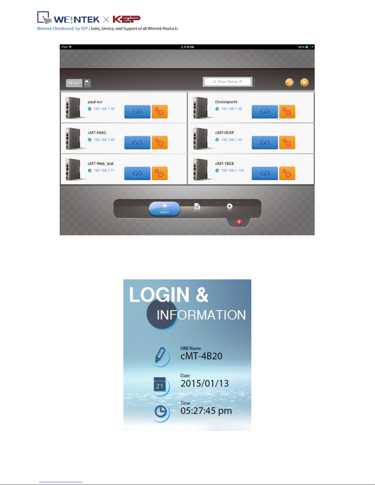
Set on iPad or Android device
Install and open cMT Viewer App on iPad or Android device.
Tap Search icon, select the cMT-SVR and tap icon to configure cMT-SVR.
Note: The default IP address of Ethernet 1: DHCP, and Ethernet 2: 192.168.100.1
cMT-SVR Startup Guide
V2.00
7
2.1 cMT-SVR System Setting
2.1.1 Information
The following part introduces cMT-SVR system information.
cMT-SVR Startup Guide

V2.00
8
Icon
Description
Displays HMI name.
Displays RTC date.
Displays RTC time.
2.1.2 System Setting
The following part introduces cMT-SVR system setting.
There are two modes, [System setting] and [Update]. [System Setting] controls all the settings while
[Update] controls limited items. For safety, confirm password before configuring. Also, before
selecting [History], enter password. History data can be downloaded when password is confirmed.
cMT-SVR Startup Guide
Table of contents
Other weintek Recording Equipment manuals

weintek
weintek cMT2158X Series User manual

weintek
weintek MT8070iER1 Series User manual

weintek
weintek cMT-3103 User manual

weintek
weintek cMT3000X Series User guide

weintek
weintek MT8000iE Series User manual

weintek
weintek cMT-SVR-200 series User manual

weintek
weintek cMT-iPC15 User manual

weintek
weintek cMT2128X Series User manual

weintek
weintek mTV series User manual

weintek
weintek cMT2108X Series User manual



