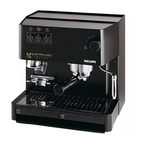
Wega Mininova User guide

MININOVA
EN ESPRESSO COFFEE MACHINE
Use and maintenance manual for the TECHNICIAN

NERO
C:0 M:0 Y:0 K:100
ROSSO
C:0 M:100 Y:100 K:0
VERDE
C:100 M:0 Y:100 K:0

3
Technical manual
ENGLISH
NERO
C:0 M:0 Y:0 K:100
ROSSO
C:0 M:100 Y:100 K:0
VERDE
C:100 M:0 Y:100 K:0
Index
A General Warnings ........................................................................... 5
B Warnings for the installer............................................................... 5
B.1 Power.................................................................................... 5
B.2 Materials to be used.............................................................. 5
B.3 Hydraulic connections........................................................... 5
B.4 Activation.............................................................................. 5
B.5 Maintenance and repairs....................................................... 6
C Typographical conventions............................................................. 6
Section I - OPERATION....................................................7
1 Technical characteristics ................................................................. 8
1.1 Internal components............................................................. 8
1.2 Internal components........................................................... 10
1.3 Push button panel Mininova 1GR Version EVD.....................12
1.4 Technical data ..................................................................... 12
2 Preparation ..................................................................................13
2.1 Unpacking the machine .....................................................13
2.2 Equipment preparation ......................................................14
3 Machine installation..................................................................... 15
3.1 Positioning..........................................................................15
3.2 Hydraulic connection
(with hydraulic connection available)
..16
3.3 Hydraulic connection (with inner tank)...............................17
3.4 Conversion from TANK to WATER MAINS 1GR Version..........19
3.5 Conversion from WATER MAINS to TANK 1GR Version..........20
3.6 Conversion from TANK to WATER MAINS 2GR Version..........21
3.7 Conversion from WATER MAINS to TANK 2GR Version..........22
3.8 Wiring................................................................................. 23
3.9 Machine start-up ................................................................23
3.10 External motor pump adjustment.......................................24
3.11 Machine tune-up ................................................................24
4 Boilers ..........................................................................................25
5 Control of the pressure in the boiler.............................................. 25
6 Automatic Water Entry .................................................................25
7 Coee delivery groups..................................................................26
8 Electronic control unit (version EVD).............................................26
9 Volumetric dosing (version EVD) ..................................................26
10 Pumping system...........................................................................27
11 Electronic push button panels (version EVD) ................................27
12 Pressure switch.............................................................................27
13 Thermostat...................................................................................27
14 Anti-ooding device.....................................................................28
15 Valve group ..................................................................................28
15.1 Valvola antidepressione ......................................................28
15.2 Safety or pressure relief valve..............................................28
15.3 Expansion-non return valve ................................................28
15.4 BY - PASS valve.................................................................... 28
16 Hot water dispensing nozzle.........................................................29
17 Steam dispensing nozzle..............................................................29
18 Softener .......................................................................................29
18.1 Description.......................................................................... 29
18.2 Measuring of the water hardness........................................29
18.4 Technical data ..................................................................... 30
18.3 Setting by-pass .................................................................. 30
19 Softener .......................................................................................31
20 Descaling......................................................................................32
20.1 1GR Version .........................................................................32
20.2 2GR Version .........................................................................33
21 Cleaning....................................................................................... 34
22 Checks and maintenance..............................................................35
23 Malfunctions and related solutions ..............................................37
24 List of hazards ..............................................................................40
Section II - ELECTRICAL/HYDRAULIC diagrams................ 41
25 Electrical schemes ........................................................................ 42
25.1 Electrical scheme versions1GR EMA-EPU............................. 42
25.2 Electrical scheme version 1GR EVD......................................43
25.3 Electrical scheme version 2GR.............................................44
26 Hydraulic schemes........................................................................45
26.1 Hydraulic scheme 1GR......................................................... 45
26.2 Hydraulic scheme 2GR......................................................... 46

4
NERO
C:0 M:0 Y:0 K:100
ROSSO
C:0 M:100 Y:100 K:0
VERDE
C:100 M:0 Y:100 K:0

5
Technical manual
ENGLISH
NERO
C:0 M:0 Y:0 K:100
ROSSO
C:0 M:100 Y:100 K:0
VERDE
C:100 M:0 Y:100 K:0
!
At the end of the installation, the installer has
to fill the "Installation Card" carryed out with
the machine. On this form must be confirmed
the conditions provided by hygiene and safety
regulations in the place of installation and must
be reported notes about changes and modication
due to a correct function of the machine.
Copies of "Installation Card" must be kept by
the user and installer until the end life of the
machine. In case of withdrawal of the machine,
the installer must provide for the withdrawal of the
"User's Installation Card".
B.1 Power
The water supply of the appliance must be carried out
with water which is suitable for human consumption, in
compliance with the regulations in force int the place
of installation. The owner / manager of the system must
conrm to the installer that the water meets the above
listed requirements.
B.2 Materials to be used
During the installation of the appliance the
components and materials that were provided with
the appliance are to be used. Should the use of other
components be necessary, the installer must verify their
suitability to be used in contact with water used for
human consumption.
B.3 Hydraulic connections
The installer must carry out the hydraulic connections
in accordance with the hygiene norms and the hydraulic
safety norms for environmental protection in force in the
place of installation.
B.4 Activation
When installation is complete, the appliance has to be
started, brought to the nominal working condition and
left for 30 minutes in the“ready to operate” condition.
Afterwards, the appliance has to be turned o and
emptied of the first water introduced in the whole
hydraulic circuit, to eliminate possible initial impurities.
Then the appliance must be once again loaded and
brought to the nominal working conditions.
After having reached the“ready to operate”condition,
the following deliveries have to be performed:
1. for each coee group make a continous erogation
to discharge all volume of water contained in each
coee tank combined;
2. release the whole volume of hot water inside the
boiler by performing a continuous delivery from the
appropriate nozzle. In the case of several dispensing
points, divide the volume on the base of the number
of the dispensing points;
3. continuously release steam for at least 1 minute for
each steam dispensing point.
AGeneral Warnings
The manufacturer of the equipment cannot be held
responsible for damage caused by failure to oblige to
the requirements below.
BWarnings for the installer
• Read this manual carefully. It provides important
information on safe installation, operation and main-
tenance of the equipment;
• Installation, conversion to other type of gas, and
maintenance of the equipment must be carried out
by personnel qualied and authorized by the manu-
facturer, in compliance with safety regulations and
instructions included in this manual;
• identify the model of the equipment. The model is
shown on the packaging and on the nameplate of
the machine;
• Install the equipment only on sites where there is
good ventilation;
• Do not obstruct the ventilation and exhaust holes on
the machine;
• Do not tamper with the equipment components.

6
NERO
C:0 M:0 Y:0 K:100
ROSSO
C:0 M:100 Y:100 K:0
VERDE
C:100 M:0 Y:100 K:0
B.5 Maintenance and repairs
After ta maintenance and/or repair intervention, the
components used must ensure that the hygiene and
safety requirements initially foreseen for the appliance
are still met. These are met by using original spare parts
only.
After a repair or a substitution of components related
to parts in direct contact with water and food, a washing
procedure has to be carried out, as in the case of rst
installation.
!This symbol indicates that you must strictly follow the
instructions it refers to, in order to avoid damage to the
appliance or injury.
iThis symbol provides additional information on the
operation of the machine and its components.
CTypographical conventions
!
The user must be sufficiently informed to operate
the appliance correctly. It is recommended not
to carry out any operations on the machine
which may modify or alter its operation.
WHEN THE MACHINE IS OPERATING, THE BOILER
CONTAINS STEAM AND HOT WATER UNDER PRESSURE.
!Themachine'sinstallationandmaintenanceoperations
can onlybe carried outbyqualied technicalpersonnel.
Qualication can be provided by the builder through
participation in specic training courses.
!The installationand maintenance of the machine must
be carried out only by qualied service personnel with
knowledge and practical experience of the machine
itself, with particular attention to the safety aspects
and hygiene.

7
Technical manual
ENGLISH
NERO
C:0 M:0 Y:0 K:100
ROSSO
C:0 M:100 Y:100 K:0
VERDE
C:100 M:0 Y:100 K:0
Section I - OPERATION

8
NERO
C:0 M:0 Y:0 K:100
ROSSO
C:0 M:100 Y:100 K:0
VERDE
C:100 M:0 Y:100 K:0
1Technical characteristics
1.1 Internal components
1. Water tank.
2. Steam knob.
3. Pressure gauge.
4. Machine main switch.
5. Anti-burn rubber.
6. Coee dispensing lever.
7. Steam dispensing nozzle.
8. Boiler heating element indicator light
working.
9. Light water level boiler.
10. Coee dispensing spout.
11. Adjustable foot.
12. Hot water dispensing knob.
13. Hot water dispensing nozzle.
14. Hot water dispensing button.
15. Push button panel.
1
3
2
9
8
4
5
6
7
13 11
12 10
VERSION 1GR
5
2
2
5
2
E
R
O
A
D
F
P
M
M
A
E
S
T
V
P
E
R
U
A
V
A
P
A
U
C
A
W
Q
A
S
E
S
E
R
W
A
T
U
E
A
1
2
3
4
5
7
EMA
EVD
5
2
2
1
2
5
7
4
11
1013
15
EPU
14 13 11 10
4
3
14

9
Technical manual
ENGLISH
NERO
C:0 M:0 Y:0 K:100
ROSSO
C:0 M:100 Y:100 K:0
VERDE
C:100 M:0 Y:100 K:0
1. Water tank.
2. Steam Knob.
3. Hot water dispensing knob.
4. Coee dispensing lever.
5. Coee dispensing spout.
6. Hot water dispensing nozzle.
7. Steam dispensing nozzle.
8. Adjustable foot.
9. Anti-burn rubber.
10. Pressure gauge.
11. Machine main switch.
12. Warning light.
E
R
O
A
D
F
P
M
M
A
E
S
T
V
P
E
R
U
A
V
A
P
A
U
C
A
W
Q
A
S
E
S
E
R
W
A
T
U
E
A
5
2
2
1 2 3 4
11
12
10 9 7 6 58
VERSION 2GR EMA

10
NERO
C:0 M:0 Y:0 K:100
ROSSO
C:0 M:100 Y:100 K:0
VERDE
C:100 M:0 Y:100 K:0
1.2 Internal components
1. Boiler.
2. Electronic control unit.
3. Water tank
(*)
.
4. Volumetric dosing device.
5. Boiler pressure gauge.
6. Dispensing group.
7. Drain pad.
8. Internal vibration pump.
9. Internal motorpump
(*)
.
* optional
8
9
1
23
4
5
6
7
VERSIONS 1GR EMA-EPU-EVD
Other manuals for Mininova
3
Table of contents
Other Wega Coffee Maker manuals

Wega
Wega ALE User manual

Wega
Wega URBAN EVDP User manual

Wega
Wega Mininova User manual

Wega
Wega Espresso Coffee Machine User manual

Wega
Wega MININOVA CLASSIC DUO 2GR User manual

Wega
Wega Polaris 1GR User guide

Wega
Wega WBAR EVD User manual

Wega
Wega MyConcept EVDP 2GR User manual

Wega
Wega Polaris EPU User manual

Wega
Wega Atlas 2010 User guide

Wega
Wega URBAN EVDP User manual

Wega
Wega MININOVA CLASSIC DUO User guide

Wega
Wega Concept User manual

Wega
Wega LB 4200 CAFFE'-CAFFE' User manual

Wega
Wega LB 4712 Operating instructions

Wega
Wega MININIVA CLASSIC DUO User manual

Wega
Wega ALE Series User manual

Wega
Wega LB 4100 User manual

Wega
Wega EMA User manual

Wega
Wega Mininova User manual