Watts tekmar 681 Installation and operating instructions

IOM-T-681
Installation, Operation and Maintenance
BACnet Snow/Ice
Sensor Interface 681
WARNING
!
Please read carefully before proceeding with
installation. Your failure to follow any attached
instructions or operating parameters may lead to the
product’s failure.
Keep this Manual for future reference.

2
Table of Contents Page
Important Safety Information ...................................................... 3
Installation
Preparation ................................................................. 4
Packaging Contents . . . . . . . . . . . . . . . . . . . . . . . . . . . . . . . . . . . . . . . . . . . . . . . . . . . . . . . . . . 4
Physical Dimensions .......................................................... 4
Installation Location .......................................................... 4
Installing the Enclosure . . . . . . . . . . . . . . . . . . . . . . . . . . . . . . . . . . . . . . . . . . . . . . . . . . . . . . . . 5
Rough-In Wiring ............................................................. 5
681 Electrical Schematic....................................................... 6
Sensor Wiring for Outdoor Sensor ............................................... 6
Communication Wiring ........................................................ 7
Access Levels............................................................... 7
User Interface
Home Screen ............................................................... 8
681 Operation............................................................... 9
Error Screen ............................................................... 11
Menu Selection ............................................................. 12
Setpoints Menu............................................................. 12
Toolbox Menu .............................................................. 13
BACnet Menu .............................................................. 14
Sensors Menu.............................................................. 14
Sequence of Operation
Snow Melting Overview....................................................... 15
Snow Detected - True/False with Snow/Ice Sensor 090 .............................. 15
Snow Detected - True/False with Snow Sensor 095 ................................. 16
Snow Detected - True/False with Snow Sensor 095 and Slab Sensor 072 ................ 16
Slab Temperature ........................................................... 16
Outdoor Temperature ........................................................ 16
Multiple Zones ............................................................. 17
Warm Weather Shut Down .................................................... 17
Cold Weather Cut Off ........................................................ 17
Slab Target . . . . . . . . . . . . . . . . . . . . . . . . . . . . . . . . . . . . . . . . . . . . . . . . . . . . . . . . . . . . . . . . 17
Troubleshooting
Error Messages.......................................................... 18 –19
Technical Data ................................................................ 19
Limited Warranty and Product Return Procedure ...................................... 20
Congratulations on the purchase of your new BACnet Snow/Ice Sensor Interface 681!
This manual covers the complete installation, programming and sequence of operation for this
BACnet Sensor Interface. You will also find instruction on testing, commissioning, and troubleshooting
the interface.
Getting Started
3
This equipment has been tested and found to
comply with the limits for a Class A digital device,
pursuant to Part 15 of the FCC Rules. These lim-
its are designed to provide reasonable protection
against harmful interference when the equipment
is operated in a commercial environment. This
equipment generates, uses, and can radiate
radio frequency energy and, if not installed and
used in accordance with the instruction manual,
may cause harmful interference to radio commu-
nications. Operation of this equipment in a resi-
dential area is likely to cause harmful interference
in which case users will be required to correct
the interference at their own expense.
This device complies with part 15 of the FCC
Rules. Operation is subject to the following two
conditions:
(1) This device may not cause harmful
interference, and
(2) this device must accept any interference
received, including interference that may
cause undesired operation.
Cet appareil numérique de la classe A respecte
toutes les exi-gences du Règlement sur le
matériel brouilleur du Canada.
It is your responsibility to ensure that this control is safely installed according to all applicable
codes and standards.
Watts is not responsible for damages resulting from improper installation and/or maintenance.
This is a safety-alert symbol.
The safety alert symbol is
shown alone or used with
a signal word (DANGER,
WARNING, or CAUTION),
a pictorial and/or a safety
message to identify hazards.
When you see this symbol
alone or with a signal word
on your equipment or in
this manual, be alert to the
potential for death or serious
personal injury.
This pictorial alerts you to
electricity, electrocution, and
shock hazards.
This symbol identifies hazards which, if not avoided,
could result in death or serious injury.
This symbol identifies hazards which, if not avoided,
could result in minor or moderate injury.
This symbol identifies practices, actions, or failure
to act which could result in property damage or
damage to the equipment.
• It is the installer’s responsibility to ensure
that this control is safely installed according
to all applicable codes and standards.
• Improper installation and operation of this
control could result in damage to the
equipment and possibly even personal
injury or death.
• This control is not intended for use as a
primary limit control. Other controls that are
intended and certified as safety limits must
be placed into the control circuit.
Radio Frequency
Interference
NOTICE
Read manual and all prod-
uct labels BEFORE using
the equipment. Do not use
unless you know the safe
and proper operation of this
equipment. Keep this man-
ual available for easy access
by all users. Replacement
manuals are available at
tekmarControls.com
Do not attempt to service the control. There
are no user serviceable parts inside the control.
Attempting to service the control voids the
warranty.
Important Safety Information
4
DIN rail
hooks
and
snaps
Tools Required
• tekmar®or jeweler flathead screwdriver
• Screwdriver for mounting hardware
• Needle-nose pliers
• Wire stripper
Materials Required
• 18 AWG, stranded solid cable (low-voltage connections)
• Four #6 or #8 screws
The following are included in the product packaging:
• BACnet Snow/Ice Sensor Interface 681
• tekmar flathead screwdriver
• 1 Installation and Operation Manual IOM-T-681
• 1 BAS Integration Manual IS-T-681
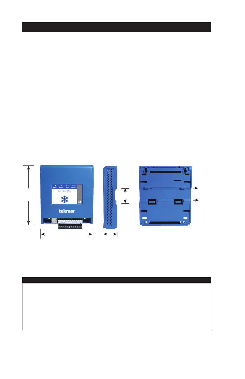
Physical Dimensions
Packaging Contents
Front View Side View
19⁄32"
(33 mm)
Mounting Base
611⁄32"
(161 mm)
51⁄8"
(130 mm)
1.46"
(37 mm)
Choose the placement of the 681 early in the construction process to enable proper wiring
during rough-in.
Installation Location
NOTICE
• Keep the 681 dry. Avoid potential leakage onto the 681.
• Maintain relative humidity less than 90% in a non-condensing environment.
• Avoid exposure to extreme temperatures beyond -4 to 122°F (20-50°C).
• Install away from equipment, appliances, or other sources of electrical interference.
• Install to allow easy access for wiring, viewing, and adjusting the display screen.
• Install approximately 5 feet (1.5 m) off the finished floor.
Installation

5
Depress the two snaps
on the bottom of the
enclosure to release the
front cover.
Secure enclosure using four #6 or #8
wood screws. Install the front cover by
hooking the top catches
and pivoting the cover
into place.
Installing the Enclosure
Installation Using Mount Holes and Screws
Mounting Screw
Snap the enclosure onto
35mm DIN rail using the
hooks and snaps on the
back of the enclosure.
Location of DIN rail hooks
and snaps on the back of
the enclosure.
Latch top hooks of
enclosure onto DIN rail.
Then rotate enclosure
down engaging bottom
snaps.
Enclosure mounted on
DIN rail (back view).
Low-Voltage Wiring
Pull two conductor 18 AWG cable, up to 500 feet
(150 m) long, for the following equipment:
• Outdoor temperature sensor (Optional)
Pull four solid conductor 18 AWG cable, up to 500 feet
(150 m) long, for the following equipment:
• Snow Sensor 095
Pull five solid conductor 18 AWG cable, up to 435 feet
(132 m) long, for the following equipment:
• Snow / Ice Sensor 090
Rough-In Wiring
To prevent the risk of personal injury and/or death, make sure power is not
applied to the interface until it is fully installed and ready for final testing. All work
must be done with power to the circuit being worked on turned off.
Please be aware local codes may require this interface to be installed or
connected by an electrician.
DIN Rail Mounting

6
Sensor Wiring for Outdoor Sensor
• Replace the front cover of the sensor enclosure. Wires from
outdoor
sensor and
sensor
common
terminals
on tekmar®
control
At the Interface:
• Connect the outdoor sensor to terminals
6 and 7.
The 681 requires the outdoor air temperature
sensor if the BAS is not providing an outdoor air
sensor. Connect the Outdoor Sensor 070 (sold
separately) to terminals 6 and 7. If the BAS has
an outdoor air sensor, this data can be shared
with the 681 through BACnet.
681 Electrical Schematic
Legend
S1 = tekmar Snow/Ice Sensor 090
S2 = tekmar Outdoor Sensor 070 (Optional)
S3 = tekmar Snow Sensor 095
S4 = tekmar Slab Sensor 072
-A, +B, G: BACnet MS/TP Communication
SD Card: FAT 32, 32GB
24 V (ac) ±10%, 50 and 60 Hz, 17 VA Class 2
S1 S2
S3 S4
24 V(ac)
MS/TP BAS Connection

7
The 681 can be connected to a Building
Automation System to automatically operate a
snow melting System. The BAS is the system
master and the 681 the system slave. BACnet
MS/TP communications uses a RS-485 connec-
tion. Use 18 AWG shielded twisted pair cable.
The maximum cable length is dependent on the
baud rate and whether terminating resistors are
installed. Refer to the BAS Integration Manual
IS-T-681 for details on the maximum recom-
mended cable length.
• Connect the A (-) terminal on the BAS network
to the RS-485 A (-) terminal 8.
• Connect the B (+) terminal on the BAS network
to the RS-485 B (+) terminal 9.
• Connect the ground (G) on the BAS network to
the RS-485 Ref. terminal 10.
Communication Wiring
The 681 is shipped pre-programmed with com-
mon settings. The 681 has an
“
Installer
”
access
level that allows full access to all settings and a
“
User
”
access level that restricts the number of
settings available. The 681 defaults is the
“
User
”
access.
To change to the
“Installer”
access level:
Step 1: Press the gear button.
Step 2: Press the Toolbox menu.
Step 3: Press Access Level menu.
Step 4: Select Installer and press save and
back button.
Access Levels

8
Snow
detected
status
Go to
menu
selection
screen
Snow
detected
symbol
Home Screen
BACnet
status
Snow/Ice
status
Slab
Temperature
status
Outdoor
Temperature
status
User Interface
9
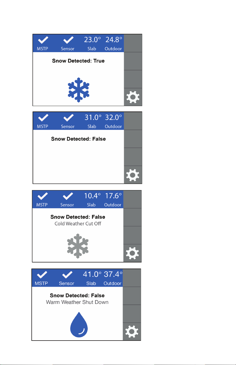
• The Snow/Ice Sensor 090 or
Snow Sensor 095 has auto-
matically detected snow or ice.
• The 681 communicates to the
BAS to signal snow or ice has
been detected.
• The Snow/Ice Sensor 090 or
Snow Sensor 095 has not
detected snow or ice.
• The 681 communicates to the
BAS to signal snow or ice is
not detected.
• CWCO is shown when the out-
door temperature is below the
CWCO temperature setpoint.
• The 681 communicates to the
BAS to signal snow or ice is not
detected due to cold temperature.
• WWSD is shown when the out-
door and slab temperature are
above the WWSD temperature
setpoint. During WWSD, the
snow will melt naturally due to
warm temperatures.
• The 681 communicates to the
BAS to signal snow or ice is
not detected due to warm
temperature.
SNOW DETECTED:
TRUE
SNOW DETECTED:
FALSE
COLD WEATHER
CUT OFF
WARM WEATHER
SHUT DOWN
681 Operation

10
• Melt Pending is shown when
the CWCO is present and the
Snow/Ice Sensor 090 or Snow
Sensor 095 detects moisture.
• The Snow/Ice Sensor 090 or
Snow Sensor 095 has detected
moisture but this condition
does not warrant snow melting
to turn on.
• The Snow/Ice Sensor 090
temperature is above 120°F
(49°C) while the snow sensor
heater is able to operate.
MELT PENDING
WATER DETECTED
SENSOR OVERHEATED
Table of contents
Other Watts Recording Equipment manuals


