WaterSoft Provectr Plus AF10AC-3 User manual
Provectr Plus
Installation / Operation Manual

2
www.watersoftinc.com
Online at
Register Your Product
Filter Specications........................................................... Page 3
Installation.......................................................................... Page 4
Programming the Control Valve....................................... Page 8
Master Programming....................................................... Page 10
Utilizing Bluetooth............................................................. Page 11
Powerhead Assembly........................................................ Page 14
Valve Body Assembly........................................................ Page 15
Bypass Assembly............................................................... Page 17
Service Instructions........................................................... Page 18
Troubleshooting................................................................. Page 19
Error Codes......................................................................... Page 20
Warranty Information....................................................... Page 21
FCC Compliance Statement:
http://www.chandlersystemsinc.com/files/FCC_Compliance_Statement.pdf
Industry Canada Compliance Statement:
http://www.chandlersystemsinc.com/files/Industry_Canada_Compliance_Statement.pdf
One or more features of this product are covered by U.S. patents, visit http://www.watersoftinc.com/patents.php
for more information.

3
WARNING
Lubricants
Do NOT use Vaseline, oils, hydrocarbon lubricants or spray silicone anywhere! Petroleum base lubricants
will cause swelling of o-rings and seals. The use of other lubricants may attack plastic Noryl®. It is recom-
mended that Dow Corning® silicone grease be used as a lubricant for all control valves. Dow Corning® 7
Release Compound is used in the manufacture of Chandler Systems control valves. (Part # LT-150)
Sealants
Pipe dope and liquid thread sealers may contain a carrier that attacks some plastic materials. It is recom-
mended that Teon® tape be used to seal plastic Noryl® threaded ttings.
Provectr Plus Specications
-How the Provectr Plus Works-
The Provectr Plus requires no chemicals for its operation. It consists of two components: (1) AP tank with
air compressor and (2) lter tank. The rst item serves to oxidize and precipitate iron and sulfur so that the
lter can later remove them. The water ows down through the mineral bed of the lter and out the service
lines. The collected precipitates must be regularly removed from the lter by reversing the ow of water
through the lter running to drain. Called “backwashing” and lasting 10 minutes, the process expands the
mineral freeing the iron, sulfur, manganese and turbidity, which are washed out of the lter to the drain. It
is important that the correct amount of water is available for the Backwash Cycle. Check pumping capacity
to be certain water is available in sucient volume to adequately backwash the equipment at the specied
rate.
General Specications AF10AC-3 AF12AC-3 AF13AC-3 AF14AC-3
Filter Media Type SmartBlend ™
Filter Media Capacity (cu ft) 1.5 2.0 2.5 3.0
Provectr® Tank Size 10 x 54 10 x 54 10 x 54 16 x 40
Mineral Tank Size 10 x 54 12 x 52 13 x 54 13 x 65
Service Flow Rate - Continuous (gpm) 5689
Service Flow Rate - Intermittent (gpm) 7 8 10 11
Backwash Flow Rate (gpm) 5.0 6.0 7.0 7.0
Gallons Used / Backwash 100 120 140 140
Space Required (D x W x H) per tank 10 x 10 x 62 10 x 10 x 62 10 x 10 x 62 16 x 16 x 73
Approximate Shipping Weight (lbs) 175 246 280 321
4
Installation
-Installation Requirements-
A/P Tank
• A level oor position between the well pump and pressure tank. (See Typical Installation Diagram.)
• DO NOT install in an area of direct sunlight or where freezing temperatures may occur!
Filter Tank
• A level oor position ahead of piping into water heater.
• Unit must be installed at least 10’ ahead of the inlet to a water heater to prevent damage due to back-up
of hot water.
• DO NOT install the unit in an area of direct sunlight or where freezing temperatures may occur! (See Typi
cal Installation Diagram.)
Relay Box
• Locate relay box near the lter tank and an unswitched 120v / 60 Hz grounded outlet
• You will notice an 8 foot meter cord and plug attached.
Note: If household plumbing is galvanized and you intend to make an installation with copper or vice ver-
sa, obtain dielectric unions to prevent dissimilar metal corrosion.
Where the drain line is elevated above the control valve or exceeds 20 ft. in length to reach the drain,
use 3/4 in. I.D. drain line tubing instead of 1/2 in.
When sweat soldering copper pipe, remember to always use lead free solder and ux. Cover yoke and
bypass valve with wet rags to prevent heat damage to connections and control valve. If using PVC or
plastic pipe, primers and solvent cements specically recommended for use for potable water are
required.
Always Follow Local Plumbing Codes.
• All plumbing lines not requiring treated water should be connected upstream of the Provectr Plus tank.
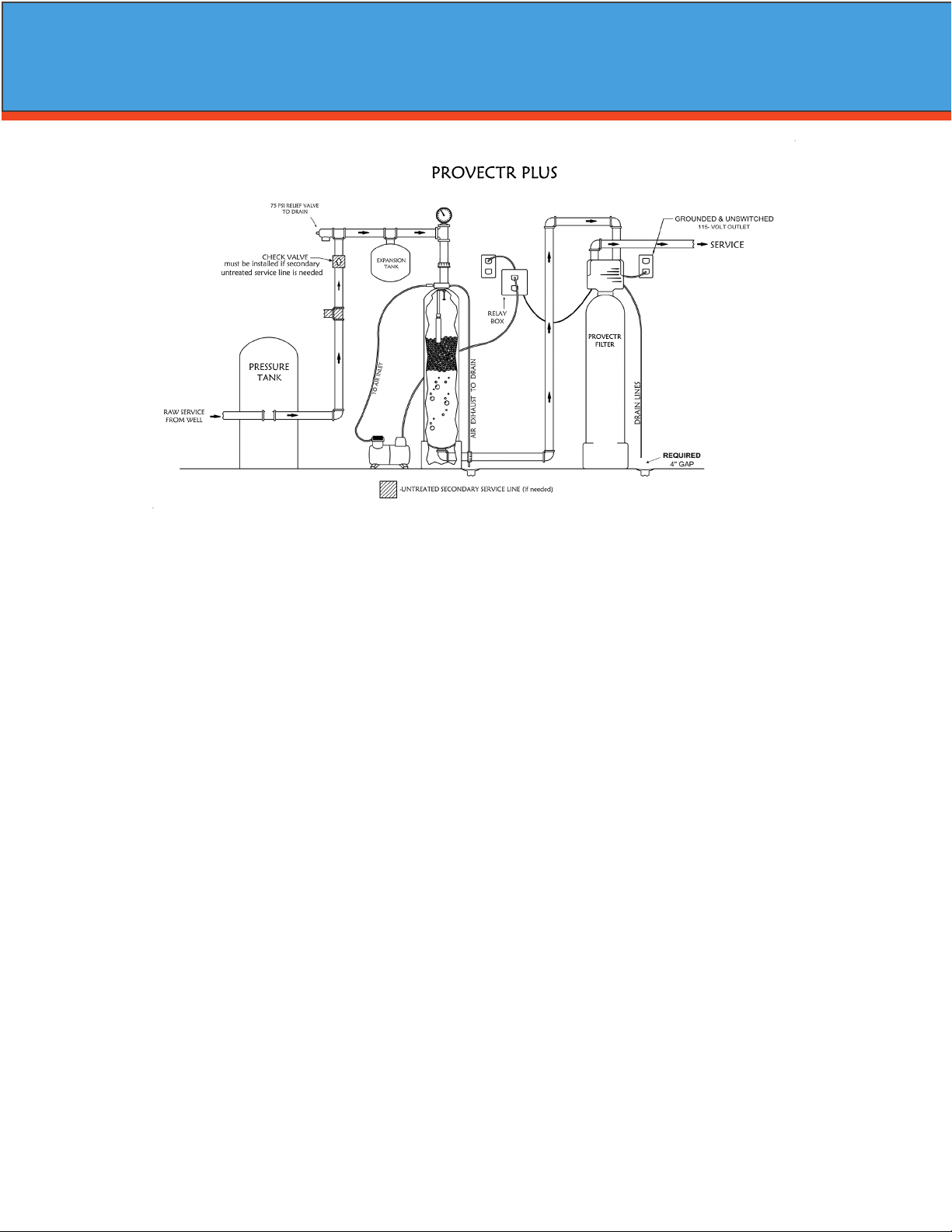
PROVECTR
FILTER
PROVECTR PLUS

5
-PROVECTR Plus Location / Other Requirements-
• Locate the lter near a 120 volt / 60 Hz grounded electrical outlet.
• Check for distance and proper drain installation (e.g. oor drain, washing machine standpipe).
• Determine type and size of piping required for PROVECTR connection (e.g. galvanized, PVC plastic).
Note: If household plumbing is galvanized and you intend to make an installation with copper (or vice ver
sa), obtain di-electric unions to prevent dissimilar metal corrosion.
Note: Where the drain line is elevated above the control valve or exceeds 20' in length to reach the drain,
use 3/4" I.D. drain line tubing instead of 1/2" I.D. Drain line tubing is not included.
Caution: When sweat soldering copper pipe (remember to always use lead free solder and ux), bypass
valve with wet rags to prevent heat damage to connections and control valve! If using PVC or plas
tic pipe, primers and solvent cements specically recommended for use with potable water are
required.
Note: All plumbing lines not requiring “ltered” water should be connected “upstream” of the A/P Tank.
(See Typical Installation Diagram.)
-Installation Procedure-
Caution: Raised arrows located on the sides of control valve body and bypass valve indicate proper direc
tion of water ow. Install inlet and outlet piping in direction of arrows. It is recommended that a
vacuum breaker be installed on the inlet plumbing.
1. Position AP tank and Filter tank at the desired location. The AP tank must be installed between the
pump/pressure tank and lter tank. If a water softener is to be installed, it should be positioned after the
lter tank.
2. The lter media is shipped separately from the lter tank and should be loaded prior to installation.
a) Remove control valve by unscrewing it from the lter tank.
b) Plug distributor with cap provided to prevent any media from entering the inside of the tube.
c) Place media funnel onto tank and ll tank 1/3 with water
d) Pour in media. Never ll tank more than 2/3 full to allow room for backwash. Since the Provectr
comes with a Vortech tank, gravel is NOT needed.
e) Remove cap and replace control valve.
3. Turn o main water supply and open nearest faucet to relieve pressure.
4. Cut main line and install the AP tank and Filter tank.
5. Turn on main water supply and allow water to ow through new plumbing and keep the nearest faucet
open to evacuate air.
6. Check for leaks.
7. If no leaks, proceed by slowly opening the bypass and allow water to ll the lter tank.
8. Allow water to run through the lter for a few minutes and then turn o the nearest faucet.
Installation
6
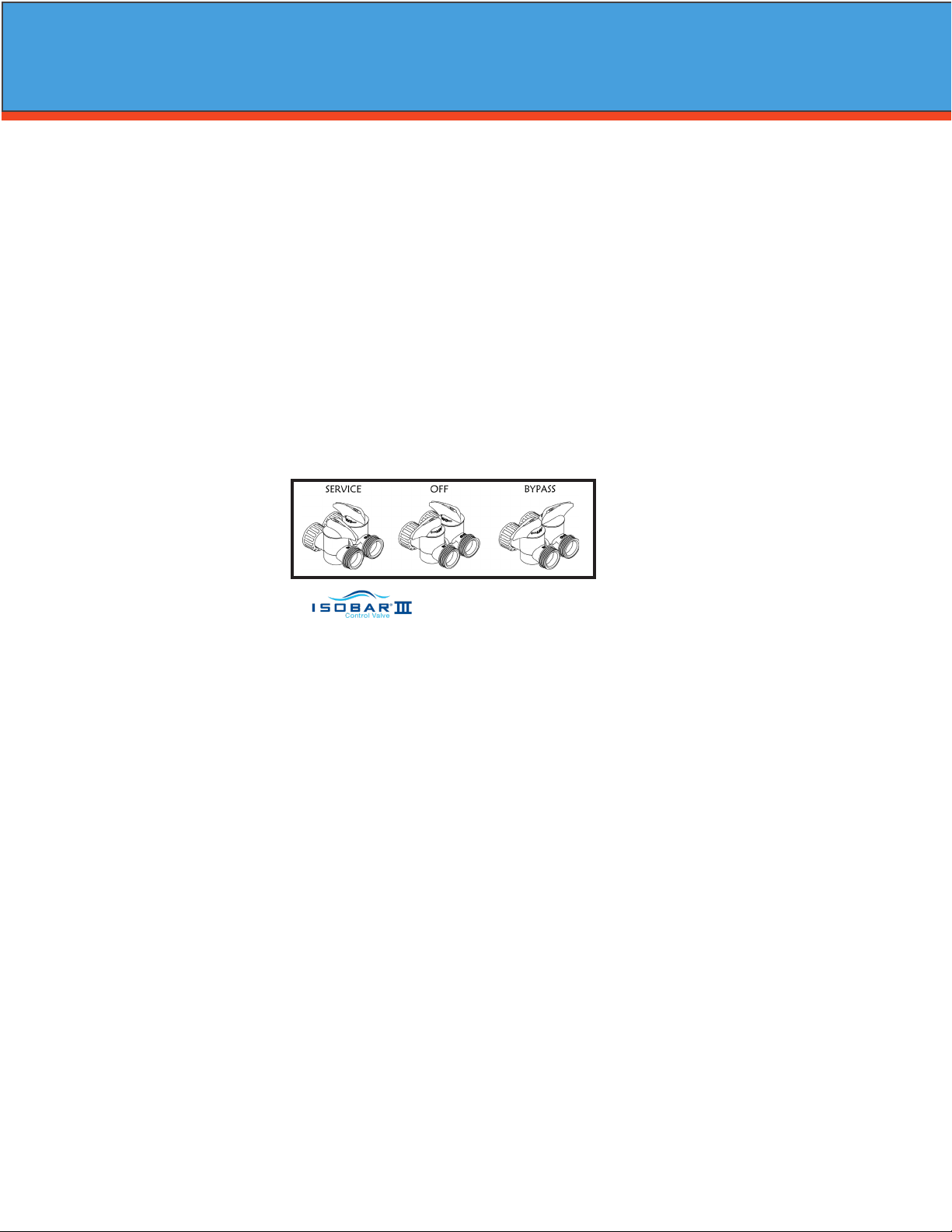
- Water Supply Connection and Bypass Valve -
To allow for servicing, swimming pool lling or lawn sprinkling, a manual Bypass Valve has been installed at
the factory. The Bypass allows raw water to be manually routed around the lter.
1. Position the A/P Tank and Filter Tank at desired location for installation. The lter tank must be installed
after the pressure tank. (See Installation Diagram.) If a water softener is to be installed, it should be posi
tioned after the lter tank.
2. The lter material is shipped separately from the Filter Tank. The Filter Tank must be loaded with material
after tank has been placed at the desired location.
A. Remove the control valve by unscrewing from the tank.
B. Use cap provided to place over top of distributor tube to prevent media from entering tube while
lling.
C. Place media funnel in hole on top of tank.
D. Pour several gallons of water in the tank. (Fill tank about 1/3 full.)
E. “D” gravel underbidding is not needed.
F. Pour in desired media to the correct level.
Note: 1/3 of the tank should be empty (Freeboard).
G. After lling the tank with media, ll the tank completely with water.
Note: This will permit the ltering material to become soaked while preparing the installation and will pre
vent the control valve from being plugged with oating material on initial backwash.
H. Remove funnel and clean lter material from tank threads.
I. Remove cap from distributor tube.
J. Replace control valve on mineral tank.
Caution: Be extremely careful to position distributor tube into control valve distributor tube pilot hole.
3. Turn OFF main water supply and OPEN nearest faucet to relieve pressure.
4. Cut main line and install appropriate elbows and extensions. Inlet connection on the A/P Tank is 1" FNPT.
The outlet is 1" MPT. Inlet is in the top of the tank and outlet is out the bottom.
Caution: Raised arrows located on the sides of control valve body and bypass valve indicate proper direc
tion of water ow. Install inlet and outlet piping in direction of arrows. It is recommended that a
vacuum breaker be installed on the inlet plumbing.
Caution: If using PVC pipe for installation of A/P Tank, assemble inlet tee before installing on tank mani
fold, to prevent excess solvent from entering A/P manifold assembly. Use only Teon based tap
and paste for threaded connections!
5. Turn handle of the bypass valve to the bypass position (horizontally).
6. Turn the main supply on to restore water service to the home.
7. OPEN nearest faucet to evacuate air and repressurize plumbing lines.
8. Check for leaks!
Bypass - Shown
Installation

7
- Electrical Connection -
1. Connect the power supply to the control valve and plug into a 115 volt / 60 Hz receptacle.
Note: Do not plug into an outlet controlled by a wall switch or pull chain that could inadvertently be
turned o.
-*Pressurizing The System -
2. Slowly rotate handle of the bypass valve to the SERVICE position.
3. Open the nearest faucet to evacuate air from plumbing lines.
4. Check for leaks! If water is observed leaking from bypass, o-rings on valve body may not be seated prop
erly. Exercise bypass valve.
5. After air is evacuated from plumbing lines, turn o faucet.
- Initial Control Valve Operation -
1. Advance control valve to BACKWASH (cycle 1) position and allow water to run to drain for 3 to 4 minutes.
Electronic Connections
P - Power Supply
B - Powered in Backwash Step Only (Cycle #1)
S - Powered in Entire Regeneration Cycle
- Drain Line Connection -
1. The drain line ow control assembly is pre-assembled for your convenience. Should you choose to hard
plumb the drain line, please remove the barb tting. The ow control housing can be removed by remov
ing the clip and pulling straight out on housing.
Note: When re-installing the drain line ow control housing, be sure you hear and feel the O-Ring pop into
place before inserting the clip.
2. Install 1/2” I.D. drain line tubing (not included) from hose barb to an open drain. A 4” gap between end of
the drain line and the open drain is required to prevent waste water backow. Keep the drain line as
short as possible. An overhead drain line can be used if necessary, but should discharge below the con
trol valve. A syphon trap (taped loop) at the outlet of the drain line is advisable to keep the drain line full
and assure correct ow during backwash. Elbows or other ttings must be kept at a bare minimum.
Note: Where the drain line is elevated above the control valve or exceeds 20 feet in length, 3/4” I.D. drain
line tubing should be used.
P B S
- Air Compressor / Relay Box –
• Locate the air compressor in close proximity to the AP tank assembly.
• Connect the supplied tubing to the compressor and the other end to the AP tank manifold insert.
• Insert the compressor’s electrical plug into the relay box.
• Insert the electrical plug from the relay box to an unswitched 120v / 60Hz grounded outlet.
• Attached by the relay box is a red and white RCA cable which plugs into the “B” and “S” outputs of the
control valve.
Note: As water ow through the lter, the meter will turn and send a signal to the relay box and the
relay box will turn on the air compressor. Make sure air compressor switch is turned on.
Installation
8
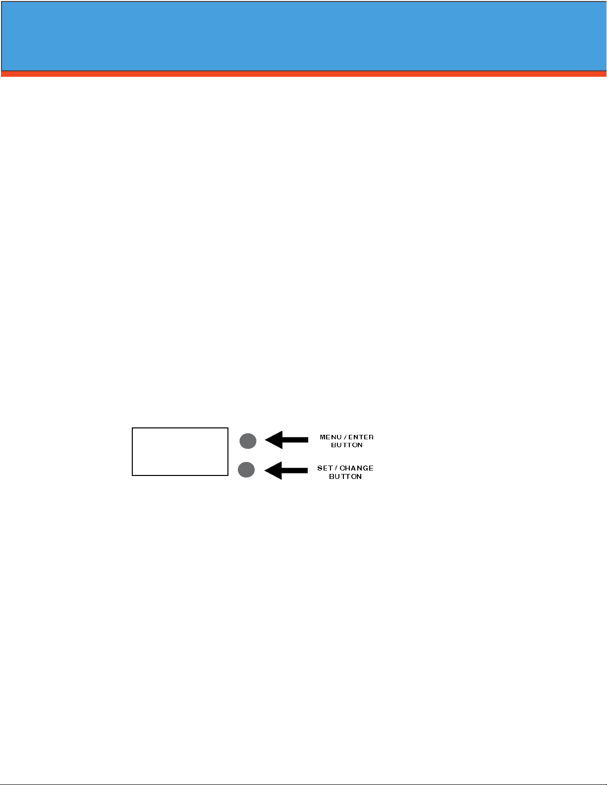
Main Menu
12:00
1. To enter Main Menu, press the Menu/Enter button.
(Time of Day will ash)
2. To set the Time of Day, press the Set/Change button.
(First digit will ash) Example (12:00)
To change digit value, press the Set/Change button.
- To accept the digit value, press the Menu/Enter button.
- Next digit will ash to begin setting.
- Once the last digit display is accepted, all digits will ash.
3. To set A.M. or P. M ., press the Menu/Enter button.
- To change digit value, press the Set/Change button. Example ( A )
- To accept the digit value, press the Menu/Enter button.
- Once A.M. or P.M. is accepted, the next menu item will ash.
4. a. To set the Number of Days between Backwash Cycles (A), press the Set/Change button.
Repeat instructions from step (2). Example ( A - 06 )
1) Maximum value is 29.
2) If value set to 0, Automatic Backwash will never occur.
3) Default setting is 6 days for lters.
- Final Checkout -
1. Be certain that the bypass valve is in Service position and main valve is completely on.
2. Check electrical supply to be certain the cord is connected to an uninterrupted 115 volt outlet.
3. REGISTER YOUR PRODUCT at www.watersoftinc.com
4. Leave this manual with the homeowner.
Important Notice - The plumbing system, piping, pressure tank, hot water tanks, softeners, etc. that have
been exposed to iron bearing water may need to be cleaned of the precipitated iron that has been collected
in them or iron bleed thru may be a problem. We suggest all tanks be drained and ushed thoroughly.
- Programming The Control Valve -
1. Set time of day.
2. Set a.m. or p.m.
3. Set number of days between backwash. (This generally will be every 4 to 6 days.)
1. Set regeneration time if other than 12:00 a.m. is desired.
Programming the Control Valve
Warning: Close handle on bypass prior to selecting the backwash position. After backwash position has
been established, slightly open valve on bypass to evacuate air from the media tank. Fully open
bypass valve when all air is depleted. This procedure will prevent media form being uplifted into
control valve.
2. Advance control valve to RAPID RINSE (cycle 3) position and allow water to run to drain for 3 to 4 min
utes.
3. Advance control valve to SERVICE (cycle 0) position.

9
Normal Operation
1. Home Display
a. Alternates between the display of Time of Day and Number of Days until the Next Backwash.
(Metered Softeners will alternate between time of days and gallons remaining until next
regeneration)
- Days Remaining until the Next Backwash will count down from the entered value until it
reaches 1 day remaining.
- A Backwash Cycle will then be initiated at the next designated regeneration time.
2. Battery Back-Up (Uses a standard 9-volt alkaline battery.)
Features of Battery Back-Up:
• During power failures, the battery will maintain the time of day as long as the battery has
power. The display is turned o to conserve battery power during this time. To conrm
that the battery is working, press either button and the display will turn on for ve (5)
seconds.
• If power failure occurs while system is regenerating, the valve will motor to a shut o posi
tion to prevent constant ow to drain. Depending upon system pressure and other factors,
it is possible to observe a reduced ow to drain during this step. After power is restored,
the valve will return and nish the cycle where it left o prior to the power interruption.
• When used without battery back-up, during a power failure, the unit stops at its current
point in the regeneration position and then restarts at that point when the power is re
stored. The time will be oset by the increment of time the unit was without power, so it is
necessary to reset the time of day on the unit. No other system will be aected.
Starting Extra Regeneration Cycle
1. To Start Delayed Extra Cycle Example ( 1 )
If Days Remaining Until Next Backwash does not read ‘1’, press and hold the Set/Change button for
3 seconds until the display reads ‘1’.
- Backwash cycle will initiate at the next designated backwash time.
2. To start Immediate Extra Cycle First complete above step.
- With Days Remaining Until Next Regeneration at ‘1’.
- Press and hold the Set/Change button.
- After 3 seconds, the backwash cycle will begin.
3. To Fast Cycle thru regeneration First complete above 2 steps.
Note:Press and hold the Set/Change button for 3 seconds to advance to the next cycle step.
Fast Cycle is not necessary unless desired to manually step through each cycle step.
(Repeat until valve returns to the home display)
Programming the Control Valve
5. To Exit Main Menu, press the Menu/Enter button.
Note: If no buttons are pressed for 60 seconds, the Main Menu will be exited automatically.

10
Master Programming Mode
Master Programming Mode
To enter Master Programming Mode, press and hold both buttons for 5 seconds.
Note: All Master Programming functions have been preset at the factory. Unless a change is desired,
it is NOT necessary to enter Master Programming Mode.
1. Regeneration Time ( r ) Example ( r 12A )
- The time of day at which backwash may take place is designated by the letter “r”.
- Default regeneration time settings is 12a
- The rst display digit indicates A.M. or P.M. To change the value, press the Set/Change button.
- Press Menu/Enter button to accept the value and move to the next digit.
- The second and third display digits indicate the hour at which the backwash will occur.
- Change the digits with the Set/Change button and accept with the Menu/Enter button.
- After the entire display ashes, press the Menu/Enter button to move to the next menu item.
2. Regeneration Cycle Step Times (Steps 1, 2, 3, 4)
Example ( 3 - 10)
- The next 4 displays set the duration of time in minutes for each backwash cycle step.
- The step number which is currently modiable is indicated on the far left of the display screen.
- The number of minutes allotted for the selected backwash step is displayed on the far right.
- Change the digit values using the Set/Change and Menu/Enter buttons as described above.
3. Bluetooth Enabled BE - 1 (ON)
BE - 0 (OFF)
4. Bluetooth Password BBPP is displayed for one second, then password is displayed.
5. To Exit the Master Programming Mode, press the Menu/Enter button until time of day returns.
Note: If no buttons are pressed for 60 seconds, the Master Programming Mode will be exited automatically.
Filters Default (Min)
Step 1 Backwash 10
Step 2 Rest 5
Step 3 Rapid Rinse 10
Step 4 Not Used 0
This manual suits for next models
3
Table of contents
Other WaterSoft Water Filtration System manuals


Popular Water Filtration System manuals by other brands

Wisy
Wisy LineAir 100 Installation and operating instructions

Schaffner
Schaffner Ecosine FN3446 Series User and installation manual

Pentair
Pentair FLECK 4600 SXT Installer manual

H2O International
H2O International H20-500 product manual

Renkforce
Renkforce 2306241 operating instructions

Neo-Pure
Neo-Pure TL3-A502 manual


