WatchDog WatchDog 3349SS User manual

Sprayer Station
PRODUCT MANUAL
Item # 3349SS
®

2
Contents
Introduction 3
Components 3
Installing the Station 4
Installing SpecWare Mobile Software 13
Configuring the WatchDog Weather Station 14
Using the WatchDog Weather Station 20
Logging Weather and GPS Data 25
Log File Format 27
Troubleshooting 28
How the Sprayer Station Works 31
Specifications 35
Copyright 2008 Spectrum Technologies, Inc.
Updated Feb 19, 2008 for 2nd Generation Connector Box

3
Introduction
Thank you for purchasing the WatchDog Sprayer Station.
The Sprayer Station is designed to provide an accurate
indication and record of the environmental conditions
around a vehicle, whether it is stationary or in motion. It
allows for real-time measurement of weather data before,
during, and after a field operation.
Components
Your WatchDog Sprayer Station package should contain
the following components:
• Sensor Unit
• Mounting Post
• Cable Assembly
• Vehicle Power Adapter
• Hook & Loop Fastener Strips (2)
• SpecWare Mobile CD
• User Guide

4
Installing
the Station
Caution: The blue metal plate and the blue film found in
the wind channel of the Sensor Unit are essential to its
operation. Be careful not to scratch the plate, puncture
the film, or damage them in any way.
Choosing the Mounting Location
The Sensor Unit must be mounted in “clear air”—away
from obstructions in any direction that will interfere with
air flowing through the unit. Ideally, this would be on the
roof of the cab or the tank. If the Sensor Unit is not the
highest point, be sure to mount it far enough from any ob-
struction so there is no interference with the air flow.

5
Because the Sensor Unit has an electronic compass, it
should be at least 3' (1 m) away from strong magnetic
fields from equipment such as radio transmitters. Since it
has a GPS, be sure it is as far as possible from high-
powered transmitting antennas to avoid mutual interfer-
ence. Similarly, mount the Sensor Unit far enough from
an existing GPS unit to avoid interference, and to keep the
Sensor Unit from blocking the GPS unit’s view of the sky.
The Sensor Unit must be installed vertically—NOT tilted
to one side. Tilting the unit will introduce an error in the
compass reading.
If you are using the magnetic mount, remember that you
must have a steel surface to attract the magnet. With a
fiberglass roof, this usually requires applying an adhesive
steel plate, as is used to provide a mounting point for GPS
units. The magnetic mount can also be removed, and a
standard ¼” bolt can be used to attach the mounting post
to the vehicle.
Once you have decided on a location, note which direction
you want the cable to travel. At this time, you may wish
to mark the front of the mounting post (the side which will
be pointing toward the front of the vehicle).

6
Assembling the Sensor Unit, Cable, and Mount
1. Gather the Sensor Unit, Mounting Post, and Cable Assem-
bly.
2. With the nut assembly on the cable near the Sensor Unit
connector, slide the cable into the cable exit slot at the top
of the Mounting Tube. Leave several inches of cable
topped by the connector above the nut assembly.
3. Screw the nut assembly onto the top of the Mounting Tube.
Hand-tighten only. Do not over-tighten. Caution: If you
want to use a thread lock, use plumber’s tape. Do not use a
liquid thread lock as it may weaken the plastic, causing it to
swell and crack.
4. Remove the protective cover from the connector, and the
warning label from the bottom of the Sensor Unit. Plug the
7-pin connector into the Sensor Unit. The alignment key on
the connector fits into a notch in the base of the Sensor
Unit.
5. Be sure the alignment tabs on the Sensor Unit are facing
forward and parallel to the centerline of the vehicle. Re-
member to orient the front of the Mounting Post forward as
well, so the cable will exit in the correct direction. Slide
the captive nut upward and screw it onto the base of the
Sensor Unit. Hand-tighten only. Do not over-tighten. Be

7
careful NOT to rotate the Sensor Unit or loosen the nut as-
sembly from the antenna mount/extension tube. Double
check to be sure the alignment tabs are still facing forward.
Alignment
Please note that for clarity the above diagram shows the sensor
alignment tabs and the cable exit both facing forward, it is un-
common for the cable to run forward from the sensor. It would
usually run to the rear or one of the sides, and the cable exit
should be aligned accordingly. The sensor itself must face for-
Temporary Mount
For temporary mounting of the Sprayer Station, slip the cable
through an open door or window. Caution: do not damage the
cable when closing the door or window. For doors, avoid the
area near the hinges as well as near the latch. Both areas exert
extremely high forces on the cable.

8
Permanent Mount
The Cable Assembly will have to be disassembled in order to
thread the cable through a hole in the wall or roof of the cab.
Although the cable will fit through a ¼” hole, a larger hole is
recommended to fit a grommet, to help ensure a watertight seal.
To disassemble the Cable Assembly:
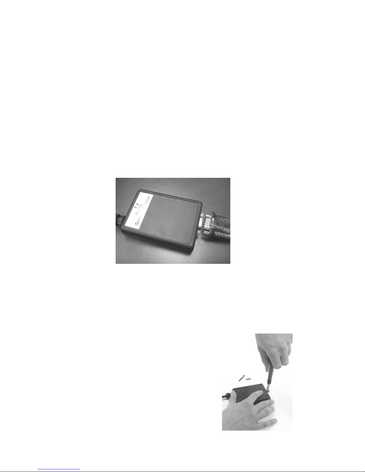
There are two versions of the connector box on the end of the
cable. The first generation box is approximately the size and
shape of a deck of cards, and has a sliding “battery cover”. The
second generation box is smaller, and is labeled as “Item
#3349CB”.
1. Open the connector box, either by sliding the “battery
cover” to remove it (first generation),
or by inserting a screwdriver in the
slots on the side and twisting to sepa-
rate the top and bottom halves (second
generation).
2. Using a small screwdriver (2 mm, 2.5
mm, or 1/10” blade – a small
“electronics” screwdriver has a 1/8”
blade which will not fit), loosen the
six screws, and remove the wires from
the terminal block.
3. Loosen the outer nut on the strain relief (first generation) or
cut the wire tie holding the cable (second generation), and
pull the cable out of the connector box.

9
First Generation Connector
Box - Terminal Block
top view end view
Second Generation Connector Box -
Interior View (with Terminal Block)
To reassemble the Cable Assembly:
1. For a first generation box, thread the cable end through the
strain relief (it can help to remove the outer strain relief nut
completely, slipping it over the cable, and reattaching it
after the cable has been threaded through the strain relief).
2. Thread the six wires into the holes on the side of the termi-
nal block, and tighten the screws to secure the wires. The
wire colors should be matched to the marked terminals as:
• TD(A) or TDA Yellow
• TD(B) or TDB Orange
• RD(A) or RDA White
• RD(B) or RDB Blue
• GND Black
• +12VDC or +12 Red
3. Hand-Tighten the outer strain relief nut (first generation),
or secure the cable with a wire tie through the two holes on
the circuit board (second generation).
4. Slide the “battery cover” back onto the connector box (first
generation), or press the two case halves together, making
sure the LEDs are under the holes next to the label (second
generation).
10
Connecting to your PDA or Laptop
Connect your PDA cable to the 9 pin serial connector on the
connector box. If you are using a laptop or other PC, the power
cable will prevent a direct connection. You must use either a 9
pin M-F serial extension cable, or if your laptop does not have a
serial port, a USB to Serial converter cable (available from
Spectrum Technologies as Item # 3661USB).
If your cable has anchor screws, use them to hold the cable se-
curely to the connector box. However, Murphy’s Law states
that it is more likely that your cable will have anchor nuts, as in
the photo below.
If you encounter this situation, perform the following steps to
connect your cable securely.
For a second generation connector box, use a wrench or pliers
to unscrew the anchor nuts. No disassembly is required.
For a first generation connector box:
1. With a Phillips screwdriver, remove
the four screws from the back of the
connector box.
2. Remove the back of the connector box.
3. Using a screwdriver and a pair of pli-
ers, remove the two nuts from the
screws holding the 9 pin serial connec-
tor .
Table of contents
Popular Irrigation System manuals by other brands

Hunter
Hunter Institutional Series instructions

Cellfast
Cellfast 52-305 user manual

Tyco Fire Product
Tyco Fire Product Star Galaxy SGQR instruction manual

Tyco Fire Product
Tyco Fire Product CENTRAL A instruction manual

Oral Care Technologies
Oral Care Technologies Hydro Floss Instructions for use

Reliable
Reliable F1-300 quick start guide


