Walker C19i User manual

Operator’s Manual
Safety, Assembly, Operating, and Maintenance Instructions
Please Read and Save These Instructions
For Safety, Read All Safety and Operation
Instructions Prior to Operating Machine
Beginning S/N: 170773
P/N 6000-38

Foreword
Thank you. . .for purchasing a Walker mower. Every eort has been made to provide you with the
most reliable mower on the market, and we are sure you will be among our many satised custom-
ers. If for any reason this product does not perform to your expectations, please contact your local
dealer. Every customer is important to us. Your satisfaction is our goal.
Please. . .read this manual thoroughly! This manual is to be used in conjunction with the engine
manufacturer’s manual for the specic engine on the mower model you have purchased. Before
you operate your new mower, please read this entire manual. Some of the information is crucial for
proper operation and maintenance of this mower - it will help protect your investment and ensure
that the mower performs to your satisfaction. Some of the information is important to your safety
and must be read and understood to help prevent possible injury to the operator or others. If any-
thing in this manual is confusing or hard to understand, please contact your local authorized dealer
or call our service department, at (970) 221-5614, for clarication before operating or servicing this
mower.
This manual covers Model C19i with the Kohler Command Pro ECH630 (19 HP) Electronic Fuel
Injection (EFI) gasoline engine.
All shields and guards must be in place for the proper and safe operation of this machine.
Where they are shown removed in this manual, it is for illustration purposes only. Do not operate
this machine unless all shields and guards are in place.
Specications given are based on the latest information available at the time this manual was pro-
duced for a tractor with standard equipment. Optional equipment is available and may aect the
standard specications listed.
Walker Mfg. Co. is continually striving to improve the design and performance of its products. We
reserve the right to make changes in specications and design without thereby incurring any obliga-
tion relative to previously manufactured products.
Sincerely,
WALKER MANUFACTURING COMPANY
Bob Walker, Chairman

Table of Contents
General Information ________________ 1
HIGHLIGHTED INFORMATION _____________ 1
GLOSSARY ____________________________ 1
IDENTIFYING NUMBER LOCATIONS ________ 1
ENGINE SERIAL NUMBER LOCATION_______ 2
SERVICING OF ENGINE AND
DRIVETRAIN COMPONENTS ______________ 2
Specications________________________ 3
ENGINE _______________________________ 3
ELECTRICAL SYSTEM __________________ 3
TRANSMISSION ________________________ 3
BLADE DRIVE__________________________ 4
TIRE SIZE _____________________________ 4
TIRE PRESSURE _______________________ 4
DRIVE BELTS __________________________ 4
SEAT__________________________________ 5
FRAME/BODY CONSTRUCTION __________ 5
GHS SYSTEM __________________________ 5
MOWER DECK _________________________ 5
TOWING _______________________________ 5
DIMENSIONS (Tractor and Mower) _________ 6
Component Identication ___________ 7
Safety Instructions _________________ 10
BEFORE OPERATING ___________________ 10
OPERATING ___________________________ 12
MAINTENANCE ________________________ 14
SAFETY, CONTROL,
AND INSTRUCTION DECALS _____________ 15
Assembly Instructions______________ 19
SETUP INSTRUCTIONS__________________ 19
Tire Installation (Tractor) _______________ 19
Battery Service _______________________ 19
Battery Charging_____________________ 20
Battery Installation ___________________ 20
Mower Deck Assembly_________________ 21
Deck Caster Wheels Installation _________ 21
Deck Discharge Chute Installation _______ 21
Deck Discharge Deector
Shield Installation ____________________ 21
PTO Shaft Guard Installation ___________ 22
Tilt-Up Roller Wheel Installation _________ 22
Mower Deck Installation on Tractor_______ 22
Deck Installation _____________________ 22
Deck Leveling _______________________ 25
DS60-3 Deck Leveling ________________ 26
Measuring Deck Levelness ____________ 26
Deck Leveling Procedure _____________ 26
PREOPERATING CHECKLIST_____________ 27
Operating Instructions _____________ 30
CONTROL IDENTIFICATION,
LOCATION, AND FUNCTION _____________ 30
Engine Throttle _______________________ 30
Forward Speed Control (FSC) ___________ 31
Steering Levers_______________________ 31
Blade Clutch (PTO)____________________ 31
Front Body Latch Release ______________ 31
Parking Brake ________________________ 33
Transmission Lockout Levers___________ 33
Engine Service Light __________________ 33
Hourmeter ___________________________ 34
Oil Pressure Warning Horn _____________ 34
Ignition Switch _______________________ 34
Light Switch (For Optional Lights) _______ 34
Circuit Breakers ______________________ 34
STARTING THE ENGINE _________________ 35
ADJUSTING GROUND
SPEED AND STEERING__________________ 35
ENGAGING THE BLADE DRIVE ___________ 37
STOPPING THE MACHINE _______________ 38
ADJUSTING CUTTING HEIGHT____________ 39
DS60-3 Cutting Height _________________ 39
DS60-3 Transport Position______________ 40
TRANSMISSION LOCKOUT ______________ 40
RECOMMENDATIONS FOR MOWING ______ 41
RECOMMENDATIONS FOR TOWING _______ 43
RECOMMENDATIONS FOR TILT-UP DECK
OPERATION/TRANSPORT _______________ 43
GRASS HANDLING SYSTEM (GHS) ________ 44
General Information ___________________ 45
Clogging Checklist____________________ 46
Using the Tilt-Up Deck _________________ 47
Using the GHS Catcher ________________ 47
Powerl ®__________________________ 47
“Full” Signal Horn ____________________ 47
Cleaning the GHS Exhaust Screen _______ 47
Dumping the Catcher __________________ 48
Tailgate Dumping ____________________ 48
Using the Dump Bag__________________ 48
Power Dump Option __________________ 49

Table of Contents
Maintenance Instructions __________ 51
MAINTENANCE SCHEDULE CHART _______ 51
IMPORTANT TIPS FOR CARE
OF THE KOHLER ENGINE ________________ 52
Fuel System _________________________ 52
Starting/Stopping _____________________ 52
Cooling System ______________________ 52
Air Cleaner System____________________ 52
Oil__________________________________ 53
LUBRICATION _________________________ 53
Engine Oil ___________________________ 53
Engine Break-In Oil___________________ 53
Checking Engine Crankcase Oil Level ____ 53
Changing Engine Crankcase Oil/Oil Filter__ 54
Mower Deck Gearbox Lubrication________ 55
Grease Fitting and Oil Point Lubrication __ 55
DS52 Mower Deck Lubrication __________ 58
Mower Deck Spindle Lubrication ________ 58
Tractor PTO Gearbox Lubrication ________ 58
Checking Gearbox Oil Level ____________ 58
Changing Gearbox Oil ________________ 58
Gear Axle Lubrication _________________ 59
Hydrostatic Transmission Oil ___________ 59
Extending the Warranty _______________ 59
Checking Hydrostatic
Transmission Oil Level ________________ 59
Changing Hydrostatic
Transmission Oil and Filter _____________ 59
CLEANING ____________________________ 61
Engine Air Cleaner System _____________ 61
Turbine Precleaner ___________________ 61
Enginaire™ VLR Air Cleaner ___________ 61
Engine Cooling System ________________ 63
Cooling Air Intake Screen ______________ 63
Cylinder Head Cooling Fins ____________ 64
Grass Buildup in Mower Deck Housing ___ 64
GHS Blower__________________________ 65
GHS Exhaust Screen __________________ 66
Hydrostatic Transmission Cooling Fins ___ 66
CHECKING/SERVICING__________________ 67
Security of Air Filtration Components ____ 67
Battery______________________________ 67
Cleaning the Terminals ________________ 67
Charging the Battery__________________ 68
Tire Pressure_________________________ 68
Wheel Bolt Torque ____________________ 68
Sharpen Mower Blades ________________ 68
Drive Belts___________________________ 69
Mower Deck Gearbox Oil Seals __________ 70
Spark Plugs__________________________ 70
Ignition Wires ________________________ 70
Fuel Lines and Clamps_________________ 70
Engine Starter________________________ 70
Transmission Control Setting ___________ 70
Neutral-Park ________________________ 70
Straight Ground Tracking ______________ 70
Blade Brake Action____________________ 70
PTO U-Joints ________________________ 71
Safety Switch System__________________ 71
Forward Speed Control Friction Lock_____ 71
REPLACING/REPAIRING_________________ 72
Drive Belts___________________________ 72
Engine PTO Drive Belt ________________ 73
Jackshaft Drive Belt __________________ 74
GHS Blower Drive Belt ________________ 75
Hydrostatic Ground Drive Belt___________ 76
Deck Drive Belt (Optional DS60-3 Deck) ___ 77
Fuel Filter ___________________________ 78
Blade Overload Shear Bolts_____________ 78
Mower Blades ________________________ 79
ADJUSTMENTS ________________________ 80
Transmission Control__________________ 80
Steering Lever Position Adjustment ______ 80
Set FSC Travel Limits (Stop)____________ 80
Set Maximum Forward
Travel Speed (Stop) __________________ 81
Neutral Function Adjustment____________ 81
Straight Ground Travel Adjustment _______ 82
Blade Clutch (PTO)____________________ 83
Clutch Engagement/Belt Tension ________ 83
Clutch Disengagement/Brake Action _____ 84
Stop Block Eccentric Adjustment ________ 85
Clutch Idler Pulley Travel Adjustment _____ 85
Blade Brake Band Adjustment __________ 86
Forward Speed Control Friction Lock_____ 87
Steering Handles _____________________ 88
Tilt-Up Deck Adjustable Stop____________ 88
GHS “Full” Signal Horn Adjustment ______ 89
MAINTENANCE AND SERVICE
RECORD SHEET_______________________ 90
Warranty _____________________ 91

General Information
1
HIGHLIGHTED INFORMATION
Walker Manufacturing recommends that any service
requiring special training or tools be performed by
an authorized Walker Mower dealer. There are sev-
eral general practices to be aware of in the area of
safety. Most accidents associated with the opera-
tion or maintenance of a Walker Mower are caused
by disregarding basic safety precautions or specic
warnings. Such accidents, in most cases, can be
prevented by being aware of the dangers present.
Information of special importance has been high-
lighted in bold type in this manual. Refer to Safety
Instructions for the meanings of DANGER, WARN-
ING, CAUTION, IMPORTANT, and NOTE.
GLOSSARY
There are many terms that are either unique to this
equipment or that are used as acronyms. The
following terms and their denitions will help while
using this manual:
●DECK is the mowing attachment mounted on
the front of the tractor which includes the carrier
frame, deck housing, belt or gear drive compo-
nents, and cutter blades.
●ELECTRONIC CONTROL UNIT (ECU)
controls
engine functions such as spark timing, fuel/air
ratio, etc.
●FORWARD SPEED CONTROL (FSC)
controls
the maximum forward speed of the tractor;
functioning as a cruise control.
●GRASS HANDLING SYSTEM (GHS®)
collects
mowed material and deposits it in the catcher.
●GRASS-PAK®SWITCH is mounted on the
grass delivery spout (in the catcher) and acti-
vates the “full” signal horn when the grass
catcher is full.
●GROUND DRIVE refers to the dual hydrostatic
transmissions which drive the main wheels.
●HYDROSTATIC TRANSMISSION transmits
and controls power from the ground drive belt
to the main drive wheel.
●LEFT HAND (LH) refers to the left-hand side of
the tractor when the operator is seated facing
forward in the tractor seat.
●POWER TAKE-OFF (PTO) transmits engine
power to run the cutter blades and GHS blower.
●POWERFIL® spreads the mowed material
throughout the interior of the grass catcher by
an oscillating delivery spout.
●RIGHT HAND (RH) refers to the right-hand side
of the tractor when the operator is seated facing
forward in the tractor seat.
●SIDE DISCHARGE (SD)
discharges mowed
material from the right side of the mower deck.
●STEERING LEVERS steer the tractor by con-
trolling the dual hydrostatic transmissions.
●TRACTOR is the prime mover, including the
engine, drivetrain, operator seat, and controls
to operate the mower.
●TRANSMISSION LOCKOUT releases the hy-
drostatic transmissions to permit freewheeling
the tractor.
●VERY LOW RESTRICTION (VLR) refers to en-
gine air cleaner system by EnginaireTM.
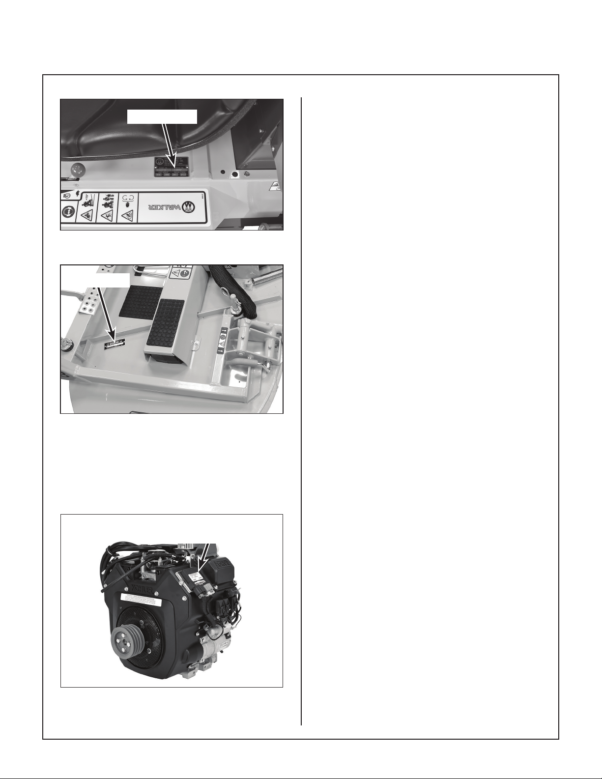
IDENTIFYING NUMBER LOCATIONS
The tractor serial number plate is axed to the trac-
tor body just below the left rear corner of the seat.
The mower deck serial number plate is axed
alongside the angle iron framing on the LH side of
the LH mower blade drive. Model and serial num-
bers are helpful when obtaining replacement parts
and maintenance assistance. For ready reference,
please record these numbers in the space provided.
Tractor Model No. ______________________
Tractor Serial No. ______________________
Deck Serial No. ______________________
Engine Model No. ______________________
Engine Serial No. ______________________
Date of Purchase ______________________
Fill In By Purchaser
General Information
2
Serial Number
Tractor Serial Number Location
Serial Number
Mower Deck Serial Number Location
ENGINE SERIAL NUMBER LOCATION
Refer to the engine manual that accompanies this
manual or photo below for the location of the engine
serial number.
Serial Number (Not Visible)
Located Under ECU
Engine Serial Number Location
SERVICING OF ENGINE AND DRIVETRAIN
COMPONENTS
The detailed servicing and repair of the engine,
hydrostatic transmission, and gearboxes are not
covered in this manual. Only routine maintenance
and general service instructions are provided. For
the service of these components during the limited
warranty period, it is important to nd a local, au-
thorized servicing agent of the component manu-
facturer. Any unauthorized work done on these
components during the warranty period may void
the warranty. If you have any diculty nding an
authorized outlet or obtaining warranty service,
please contact our Service Department for assis-
tance:
Walker Manufacturing Company
5925 E. Harmony Road
Fort Collins, CO 80528
1-970-221-5614
www.walker.com
Service manuals are available for each of these
components from their respective manufacturers as
follows:
Kohler Engines Kohler Company
Kohler, WI 53044
800-544-2444
www.kohlerengines.com
Hydrostatic Danfoss Power Solutions
Transmissions 14615 Lone Oak Road
Eden Prairie, MN 55344 USA
952-937-9800
www.danfoss.com
Gearboxes (Deck) Peerless Gear
1555 South Jackson St.
Salem, IN 47167 USA
866-536-8310
www.peerlessgear.com

Specications
3
MODEL C19i
ENGINE
Manufacturer/Model Kohler Command Pro® ECH630, 2 Cyl., Gasoline (Air-Cooled),
Electronic Fuel Injection (EFI)
Displacement cu. in. (cc) 42.4 (694)
Max. Power HP (kW) 19.0 (14.2) @ 3600 RPM
Governed RPM 3600
Max. Torque lb·ft (N·m) 34.2 (46.4)
Idle RPM 1200
Spark Plug Type Champion® RC12YC
Spark Plug Gap in. (mm) .030 (0.76)
Crankcase Capacity qt (L) 1.8 (1.7)
Crankcase Lubricant
(From Factory)
300 Hour, Kohler PRO® Synthetic 10W-50 Kohler P/N 25 357 72-S
Oil Filter (From Factory) 300 Hour, Kohler PRO® Filter P/N 25 050 53-S
Conventional Crankcase Lubricant
(Alternative Option)
100 Hour, API SJ or Higher Grade Oil Only with 10W-30 Viscosity
Above 0° F (-18° C), or 5W-20 or 5W-30 Viscosity Below 32° F (0° C)
Oil Filter (Alternative Option) 200 Hour, Kohler Filter P/N 28-050-01
Cooling System Air-Cooled
Fuel Tank Capacity gal (L) 4.0 (15.1)
Fuel Regular Grade Unleaded Gasoline
(87 Octane Minimum, 10% Ethanol Maximum)
Air Cleaner Remote Mounted EnginaireTM VLR
(Walker P/N 5090-6 Primary/5090-5 Safety Filter)
ELECTRICAL SYSTEM
Battery 12 Volt, 350 CCA (Interstate SP-40)
Charging System Flywheel Alternator
Charging Output 25 Amp DC (Regulated)
System Polarity Negative Ground
Ignition Electronic Capacitive Discharge
Starter 12 Volt Electric Ring-Gear Type, Solenoid Shift
Interlock Switches Ignition Lockout by Seat Switch, Transmission Neutral,
Blade Clutch, and Parking Brake
Circuit Breaker Auto Reset (30A)
Manual Reset (7A) - Front Panel
TRANSMISSION
Manufacturer/Model Dual Hydrostatic, Danfoss Model 7, Each Wheel Independently
Driven
Steering Hand Lever Control / Individual Wheel
Forward Speed Control Precision Friction Lock Lever, Cruise Control, with
Neutral-Park Position
Service Brake Dynamic Braking through Hydrostatic Transmission(s)

Specications
4
MODEL C19i
TRANSMISSION (continued)
Parking Brake Mechanical Pin Lock in Transmission Gear
Neutral Transmission Release by Manual Dump Valve
Hydrostatic Transmission Oil
Transmission Oil Filtration Walker Transmission Oil Performance System (TOPSTM)
Factory Service Mobil SHCTM 630, Walker P/N 6450-20
Transmission Filter Walker P/N 5024-13
Transmission Oil Capacity oz (L) 80 (2.4)
Transmission Cooling Cooling Fan Mounted on Drive Pulley
Final Drive Oil (Gear Axle)
Final Drive Gear Drive Axle
Factory Service SAE E.P. 80W-90 (API GL-5) Gear Lube
Final Drive Oil Capacity oz (L) 24 (0.71)
Ground Travel Speed
Forward MPH (km/h)
Reverse MPH (km/h)
0-7 (0-11) Innitely Variable
0-5 (0-8) Innitely Variable
BLADE DRIVE
PTO Shaft Quick Disconnect Sliding Spline Shaft with Two (2) High-Speed
U-Joints
Blade Drive Clutch and Brake Manual Belt Tightener Clutch and Band Brake
[Stops Blades within Five (5) Seconds of Disengagement]
TIRE SIZE
Deck Caster Wheel 8 x 3.00-4 Semi-Pneumatic (Standard)
8 x 3.00-4 Pneumatic 4-Ply (Optional)
11 x 4.00-5 Pneumatic 6-Ply (DS52 and DS60 Only)
Drive 18 x 8.50-10 (Pneumatic 4-Ply, Low-Prole)
18 x 7.00-8 (Pneumatic 4-Ply, Optional)
Tailwheel 13 x 6.50-6 (Pneumatic 4-Ply)
TIRE PRESSURE PSI (KPA)
Deck Caster Wheel* 20 (137)
Drive 15 (103)
Tailwheel 20 (137)
* If equipped with optional pneumatic tires
DRIVE BELTS
Engine PTO Walker P/N 8230
Jackshaft Drive Walker P/N 6250-1
Ground Drive, Micro-V Walker P/N 7248
Blower Walker P/N 7234-2

Specications
5
MODEL C19i
SEAT Contour-Molded, with Nylon Backed Vinyl Cover and Integral
Foam Cushion
FRAME/BODY CONSTRUCTION
Frame All Welded Unitized Steel Chassis
Body 14 Gauge Steel
Deck 11 Gauge Steel
GHS Catcher and Chutes Molded Cross-Linked Polyethylene (High Impact Material,
UV Stabilized) for Chutes and Linear Low-Density Polyethylene for
Catcher
GHS SYSTEM
Blower 10.5 in. Diameter, Three-Blade Paddle Wheel
Blower Brake Band Brake [Works in Combination with PTO Clutch, Stops
Blower within Five (5) Seconds of PTO Disengagement]
Max. Blower RPM 4000
Grass Catcher Capacity
gal / bu / L
65 / 7 / 246
Full Signal (Grass-Pak® Switch) Oscillating Vane Switch Mounted on Grass Delivery Spout Triggers
Horn Signal
Powerl®Oscillating Delivery Spout Driven by 12 Volt Electric Gearmotor
Spreads Material throughout Interior of Catcher @ 35 Cycles/Min
MOWER DECK
Recommended Cut Width
Collection 36 to 52 in. (91 to 132 cm)
Side Discharge 36 to 60 in. (91 to 152 cm)
Mulch 36 to 52 in. (91 to 132 cm)
Cutting Height 1.5 to 4 in. (4 to 10 cm) or
1.5 to 4.5 in. (4 to 11.5 cm) (DS52 & DS60 Belt-Driven Decks Only)
Deck Suspension Independent Torsion-Flex Frame with Caster Wheels and
Counterweight Springs
TOWING
Towing Capacity lb (kg) 250 (113) if equipped with a factory installed or factory authorized
tow hitch

Specications
6
MODEL C19i
DIMENSIONS (Tractor and Mower)
Length in. (cm)
Tractor Only 64.5 (164)
Tractor Wheel Base 41 (104)
Tractor with Tilted Deck
(Approximate)
77 (196)
Tractor with 42" Collection Deck
(DC42-1)
89.25 (227)
Width in. (cm)
Tractor Only (Outside Tire) 37.75 (96)
Tractor with 42" Collection Deck
(DC42-1)
43.25 (110)
Height in. (cm)
Tractor 47.5 (121)
Weight lb (kg)
Tractor Only 739 (335)
Tractor with 42" Collection Deck
(DC42-1)
930 (422)
NOTE: The manufacturer reserves the right to make changes in specications shown herein at any time
without notice or obligation. The specications listed are for a standard conguration tractor, and may
change with the addition of optional equipment.
Other manuals for C19i
2
Table of contents
Other Walker Farm Equipment manuals