Vogt L Series User manual

2
Introduction
This manual deals with the installation, operation and maintenance of VOGT S.A. L
series centrifugal pumps.
This model is a multistage centrifugal pump, with closed impeller, radial flow with
horizontal axis, cylindrical diffuser type casing, with lateral horizontal suction and
vertical discharge upwards. The suction and discharge ports are for nominal pressures
PN-16 and PN-40, PN-64 according to DIN 2543, DIN 2545, DIN 2546 respectively.
The operation of a centrifugal pump, chosen in accordance with all the technical background, can give poor service for
various reasons. This is generally due to poor installation and/or operation of the pumping equipment.
Efficient service is only achieved by installing and operating the pumping equipment correctly, therefore, the instructions
in this manual must be fully complied with. Pumps should not be used for purposes other than the service conditions
stipulated at the time of purchase.
The nameplate attached to the pump describes the most important features of the equipment purchased.
The design, materials, and workmanship incorporated in the construction of VOGT pumps allow for a long, trouble-free
service life. The life and satisfactory performance of VOGT pumping equipment, in any case depends on a correct
application, installation and also on a periodic inspection and careful maintenance.
VOGT S.A. will not be responsible for physical injury, damage or other inconvenience caused by improper installation,
operation or maintenance.
The warranty is only valid when the equipment is used for the application for which it was ordered.
In case of any doubt or additional information regarding the installation, operation or maintenance of the pumping
equipment, contact qualified technical personnel by calling the head office or any authorized distributor.
VOGT S.A., reserves the right to make changes at any time without notice and without incurring any obligation.
The contents of this publication are based on the latest product information at the time of going to press.
No part of this publication may be reproduced without written permission from VOGT S.A.
This manual should be considered a permanent part of the pump and should remain with the pump if sold.
Introduction
3
Safety
Instructions
Indicates a procedure, operation, etc., with a strong possibility of severe personal injury, loss of life or irreparable
damage to equipment, if not performed properly.
Indicates a procedure, operation, etc., with a strong possibility of severe damage to the pumping equipment, if not
performed properly.
THE CONTENTS OF THIS MANUAL MUST BE READ AND UNDERSTOOD BEFORE INSTALLING AND OPERATING THE PUMPING
EQUIPMENT. CAREFULLY READ AND UNDERSTAND THE MOTOR MANUAL, ATTACHED TO THIS MATERIAL, PROVIDED BY THE
MOTOR MANUFACTURER, BEFORE OPERATING THE PUMPING EQUIPMENT.
•Learn how to stop the pumping equipment quickly and understand the operation of all controls. Do not allow
pumping equipment to be used without proper instructions.
•Never place your hands, feet or any part of your body near rotating or moving parts.
•Never operate the pumping equipment if any protection of the rotating parts is missing.
•Never operate the equipment without first charging and verifying the correct oil level in the bearing body, in
models that use oil lubrication.
•To ensure the correct lubrication of both bearings, it is required that the equipment is correctly leveled
(horizontal).(horizontal).
•Always keep the pump at least one meter away from building walls or other equipment during operation to avoid
fire and to provide adequate ventilation.
•Always perform inspection before starting the pump. In this way you can avoid an accident or damage to the
equipment.
•Children and domestic animals should not go near the place where the pump operates, let alone touch it, because
they could be injured by touching the equipment activated by the motor.
•Never place flammable items such as fuel, matches, etc., near the pump while it is running.
•Never place objects or items of any kind on the motor or pump, as this may create a fire hazard.
•Always maintain good cooling air circulation if the pump is to be operated in a small room.
!CAUTION
NOTE
!WARNING
!WARNING
2.1 Definitions
Provides useful information regarding a procedure, operation, etc., that facilitates the correct use of the pumping
equipment.
2.2 General Safety Considerations
Safety Instructions

4
Safety
Instructions
Safety Instructions
2.3 Qualification and Training of Operating Personnel
Personnel responsible for operation, maintenance, inspection and assembly must be suitably qualified and authorized.
The scope of responsibility and supervision of the personnel must be exactly defined by the plant operator. The plant
operator must ensure that the operating instructions are fully understood by the personnel.
2.4 Risks due to Non-Compliance with Safety Instructions
VOGT S.A. declines all responsibility that may arise from not respecting the safety standards in force at any time, during
the handling, installation or operation of its equipment.
The working conditions indicated in the order cannot be modified. Should this occur, VOGT S.A. must be informed.
Improper use outside the working conditions, or assembly/disassembly by untrained personnel may result in risks to
life, the pump and other accessories in use or normal operation of the equipment.
In order to benefit during the warranty period from the Guarantee offered by VOGT S.A., it is necessary to:
•The instructions in this manual have been correctly followed.
•The equipment is disassembled only by authorized personnel of our Technical Assistance Services or
directly by our factory personnel.
Any modification of the equipment must be previously consulted with VOGT S.A. For safety reasons, spare parts and
accessories authorized by VOGT S.A. must be used. The use of non-original spare parts exempts VOGT S.A. from any
responsibility.
!WARNING
Equipment
Description
Equipment Description
- 10 -
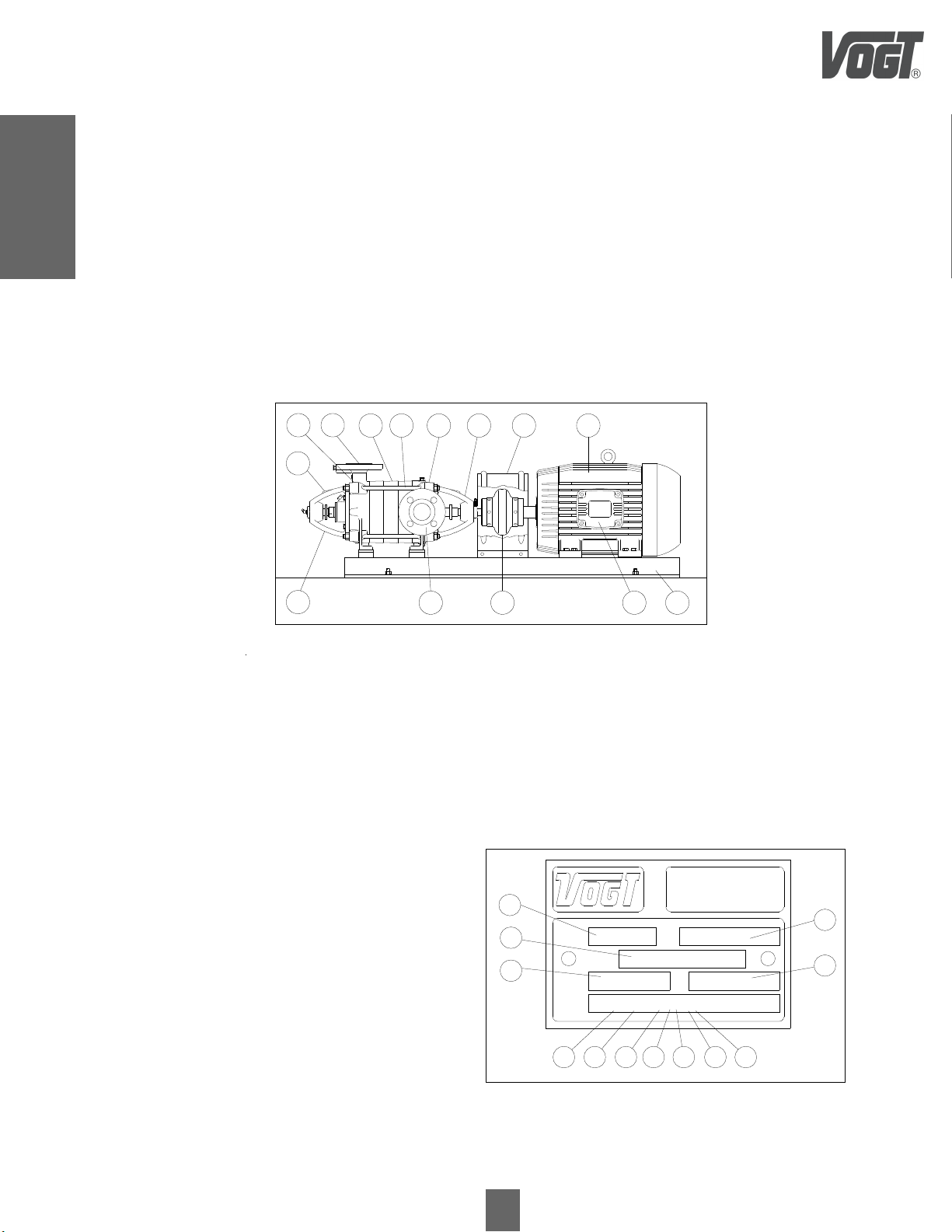
Figure 1
3.1 Pumping Equipment, Main Components
1. Discharge Pump Body
2. Discharge Nozzle
3. Stage Body
4. Tightening stud Stages
5. Suction Pump Body
6. Suction Bearing Body
7. Tap Cover
5
3.2 Identification Plate
The operation of a centrifugal pump, chosen in accordance with all the technical background, can give poor service for various
reasons. This is generally due to improper installation or mishandling of the pumping equipment.
Efficient service can only be achieved by installing the pump correctly, therefore, the instructions in this manual must be
complied with in their entirety. Pumps should not be used for purposes other than the service conditions stipulated at the time
of purchase. The nameplate installed on the pump describes the most important features of the equipment purchased:
1. Serial Number
2. Flow rate (m³/h)
3. Curve Type
4. Number of Stages
5. Sealing Type
6. Type of Execution
7. Pump Mat.
8. Pump Model
9. Series
10.Head (m.w.c.)
11.Speed (r.p.m.)
12.Year of manufacture
Figure 2
8. Electric Motor
9. Base
10. Junction Box
11. Flexible Coupling
12. Suction Mouth
13. Discharge Bearing Body
14. Identification Plate
1 2 3 4 5 6 7 8
9
10
11
13
14
12
L 50 FES 6A
2840
INDUSTRIA MECANICA
VOGT S.A.
ALVAREZ DE TOLEDO 669
SANTIAGO - CHILE
59 Q
H
COD.
m.c.a.
2004
AÑO
n2.900
N°
50 m 3
/ h
R.P.M.
10
11
12
489 7 6 5 3
1
2

6
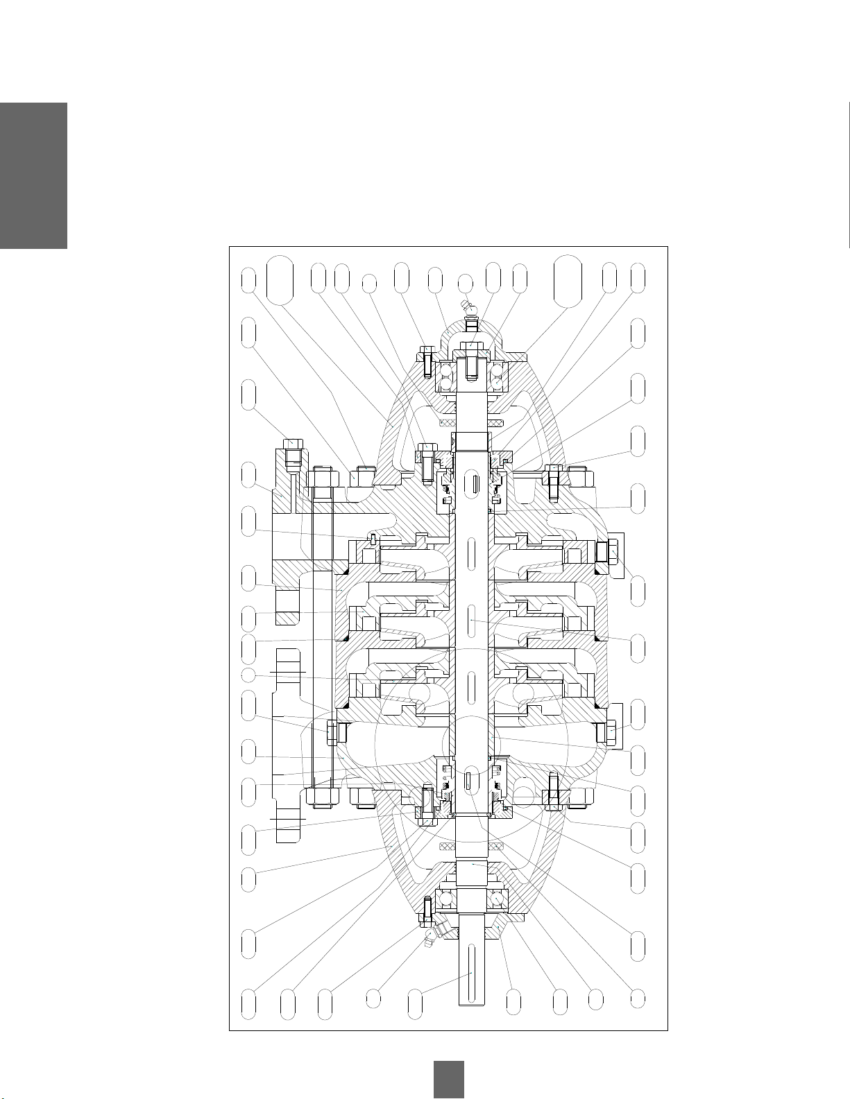
3.3 Centrifugal Pump
3.3.1 L Series Sectional Cutting Model 25-Cast Iron and Bronze Execution
24.0
5/24.
06
Figure 3
2.02 30.0930.03 2.082.09114.0430.1111.0118.0224.02
4.01
10.13
5.10
28.17
10.02
5.03
24.04
9.03
7.n
38
10.03
19.11 28.06/29.05/26.04 25.08 30.04 10.01 19.08
28.03 27.n
14.05
30.11
4.03/4.04
11.02
18.03
35
5.05/5.06
24.05/24.06
9.05/9.06
38
28.0930.06 25.08 26.04/29.05/28.06
24.07
19.0919.11
2.01
19.09 18.06
29.04
Equipment
Description
7
Equipment
Description
Equipment Description
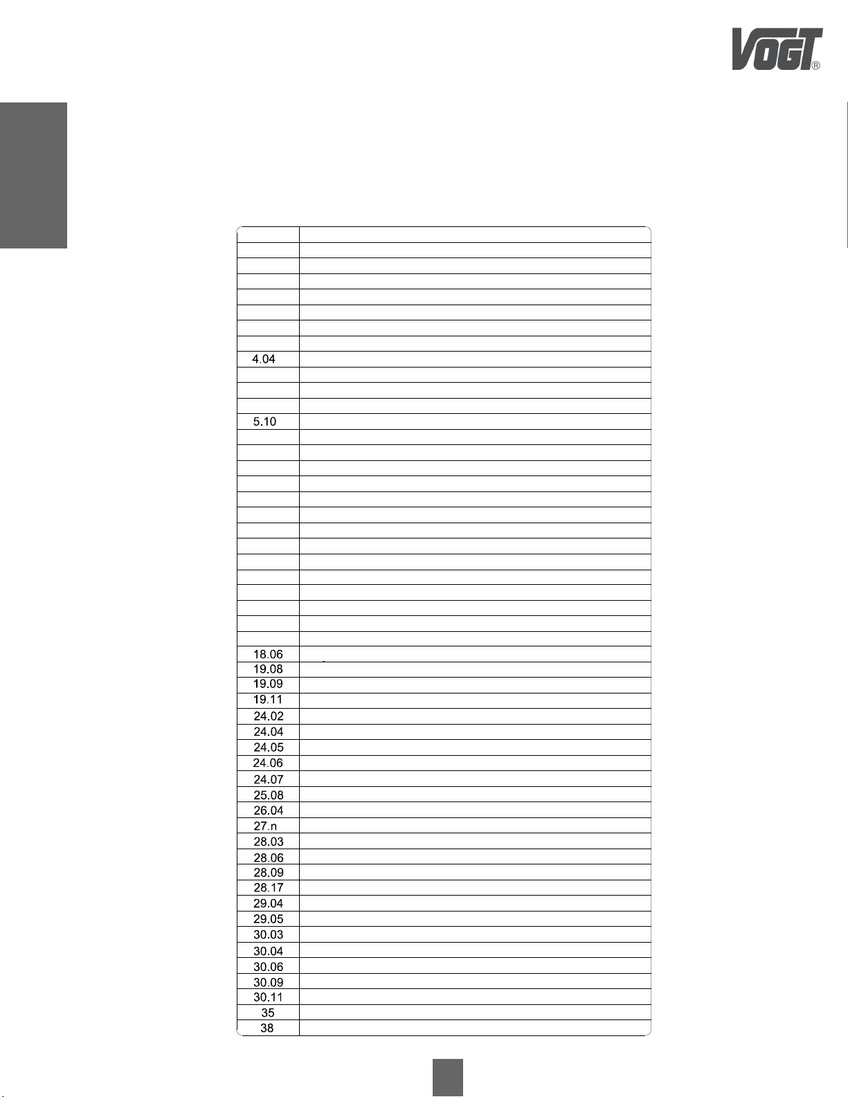
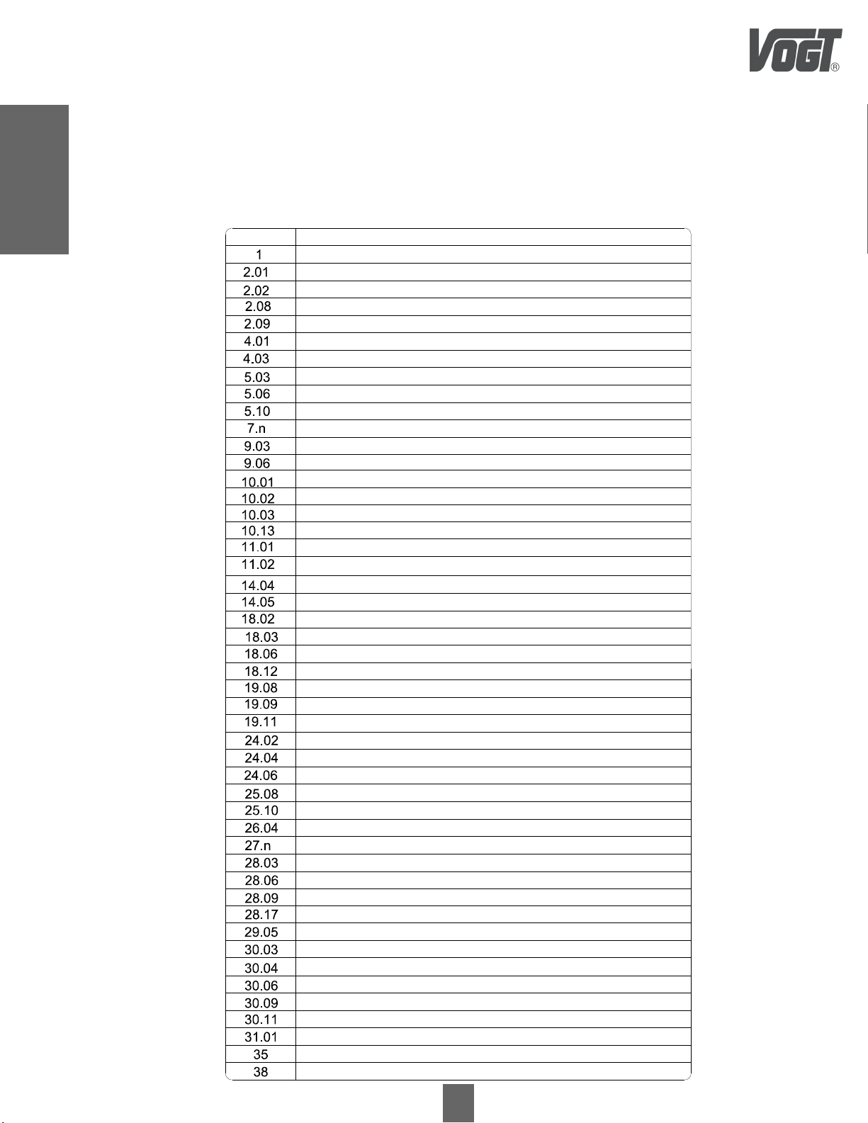
3.3.2 Description of L Series Centrifugal Pump Parts and Pieces
Model 25 - Cast Iron and Bronze Execution
Suction Side Bearing
9.03
Shaft for "n" Stages PS Seal and Cable Glands
7.n
Blind Cover Bearing Body 6 to 10 Stages
5.06
Blind Cover Body Bearing Body 2 to 5 Stages
5.05
Perforated Cover Bearing Body
5.03
Body Bearing Discharge Side 2 to 5 Stages
4.03
Body Stage
2.08
Discharge Pump Body
2.02
Suction Pump Body
2.01
Impeller
1
Unloading Side Seal Holder Box
14.05
Suction Side Seal Holder Box
14.04
PS Mechanical Seal Discharge Side (Balanced)
11.02
PS Mechanical Seal Suction Side
11.01
Polin Antigiro10.03
Taps
10.02
Impeller Key
10.01
Discharge Side Bearing 6 to 10 Stages
9.06
Discharge Side Bearing 2 to 5 Stages
9.05
18.03
18.02
Suction Side PS Seal Bushing
4.01
Suction Side Bearing Body
2.09
Guiding Crown
PS Seal Bushing Discharge Side
Pin Perforated Cover Body Bearing
10.13
Table 1
Denomination
Number
Body Bearing Discharge Side 6 to 10 Stages
Grease Cap
Spacer bushing PS seal and packing gland
Oring body stage
Oring seal bushing
Oring seal housing / Pump body
Elastic ring
Seager locking perforated cover bearing body
Seager safety cap blind cover bearing body 2 to 5 stages
Seager safety cap blind cover bearing body 6 to 10 stages
Seager axle insurance
Bearing body bolt / Pump body
Seal housing stud / Pump body
Clamping bolt for "n" stages
Tightening stud nut
Nut for housing / Pump body
Nut lock shaft
Special grease fitting nut suction side
Spacer sleeve
Pressure tapping screw /Pump body
Suction side priming plug
Suction side drain plug
Drain plug discharge side
Pressure tapping plug
Seal holder box plug 2 to 5 stages
Grease fitting for bearing body cover
Golilla water cutter

8
Equipment
Description
Model 25 - Stainless Steel AISI 316 execution
3.3.3 L Series Sectional Cutting
Figure 4
30.03
14.04
30.1111.0118.0224.02
4.01
10.13
5.10
28.17
10.02
5.03
24.04
9.03
7.n
10.03
38
19.11 28.06/29.05/26.04 25.08 18.06 30.04 10.01 19.08
2.022.082.0918.121 30.09 28.03 27.n 14.05
30.11
4.03
11.02
18.03
35
5.06
24.06
31.01
25.10
30.06 25.0826.04/29.05/28.06 19.11 19.09
28.09
38
9.06
2.01
19.09 18.12
9
Equipment
Description
Table 2
Equipment Description
3.3.4 Description of L Series Centrifugal Pump Parts and Pieces
Model 25 - Stainless Steel AISI 316 execution
Denomination
Number
Impeller
Suction pump body
Discharge pump body
Body stage
Steering crown
Suction side bearing body
Discharge side bearing body
Perforated bearing body cover
Blind cover bearing body
Grease cover
Shaft for "n" stages PS seal and cable gland
Suction side bearing
Discharge side bearing
Drive key
Cotter pin
Anti-spin polyn
Pin drill cover bearing body
PS mechanical seal Suction side
PS mechanical seal discharge side (Balanced)
Seal holder box suction side
Seal holder box discharge side
PS suction side seal bushing
PS seal bushing discharge side
Spacer bushing seal PS and PE
Cermized spacer bushing impeller
ORing body stage
ORing seal bushing
ORing seal housing / pump body
Elastic ring
Seager locking perforated cover bearing body
Seager safety cap blind cover bearing body 6 to 10 stages
Bearing body bolt / Pump body
Shaft end stop bolt
Seal housing stud / Pump body
Clamping bolt for "n" stages
Tightening stud nut
Nut for housing / Pump casing
Axle lock nut
Special grease fitting nut suction side
Pressure tapping screw / Pump casing
Suction side priming plug
Suction side drain plug
Discharge side drain plug
Pressure tapping plug
Seal holder box plug 2 to 5 stages
Shaft end stop
Grease fitting for bearing body cover
Golilla water cut
10
Equipment
Description
30.0311.0115.044.0118.02
24.02
25.03
35
10.02
5.03
9.03
7.n
10.0338
2.022.082.0919.081
19.10 19.0925.08
25.11 30.09 28.03 27.n
4.10/4.11
15.05
25.11
38
25.03
5.04
35
25.10
31.01
9.09/9.10
28.09
11.0210.0130.04 30.06 19.09 25.08 18.03 19.10
10.042.01
18.06
4.12/4.13
9.07/9.08
Figure 5
Equipment Description
3.3.5 L Series Sectional Cutting
Model 32-40 and 50 - Cast Iron and Bronze Construction
Table of contents
Other Vogt Water Pump manuals


Popular Water Pump manuals by other brands


Sykes AmeriPumps
Sykes AmeriPumps GP100M Operation and maintenance instructions

DUROMAX
DUROMAX XP WX Series user manual

BRINKMANN PUMPS
BRINKMANN PUMPS SBF550 operating instructions

Franklin Electric
Franklin Electric IPS Installation & operation manual

Xylem
Xylem e-1532 Series instruction manual

Milton Roy
Milton Roy PRIMEROYAL instruction manual