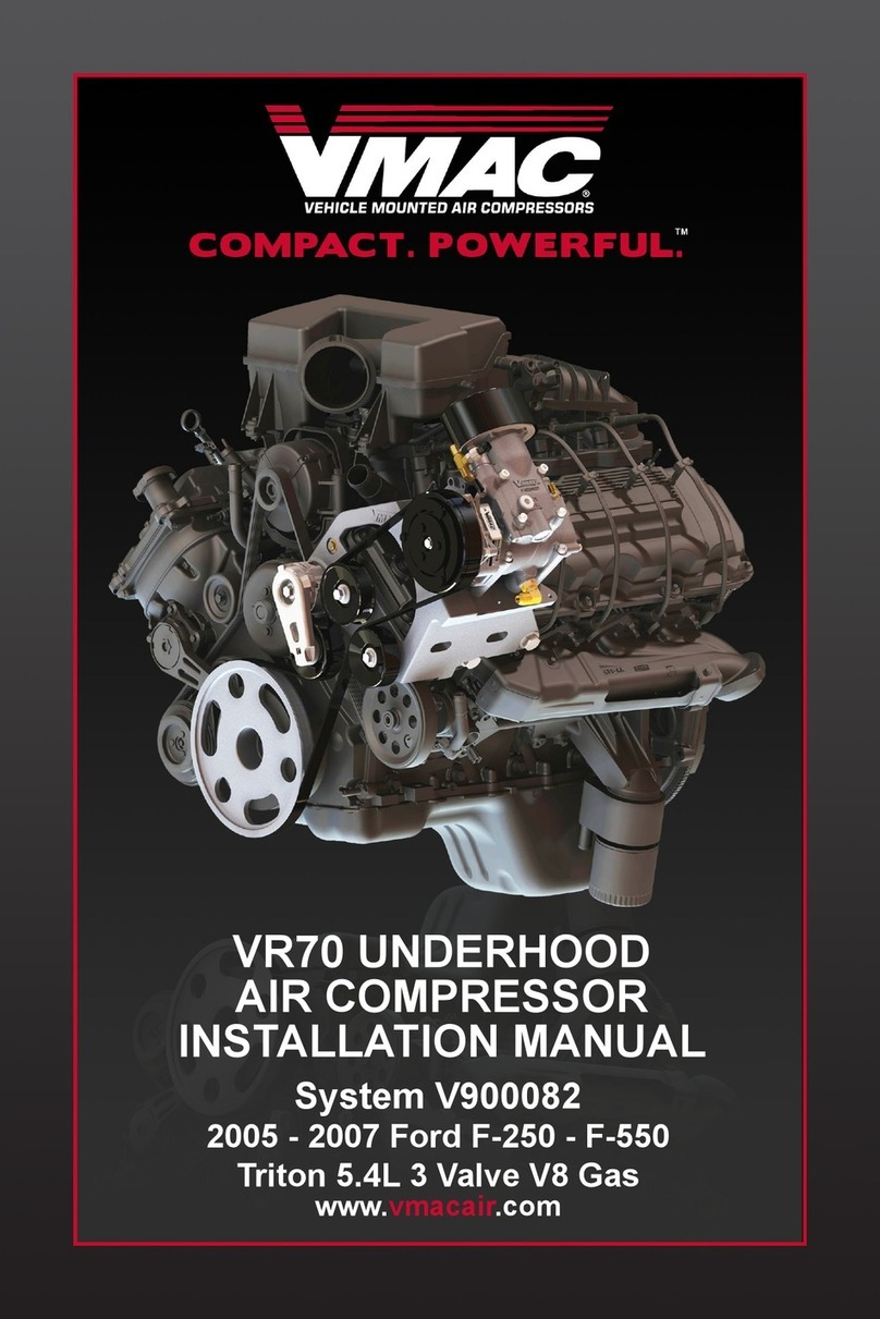
Vmac VR70 User manual

System V900083
2005 - 2006 Ford E-250 - E-350
5.4L Triton V8 Gas
www.vmacair.com
VR70 UNDERHOOD
AIR COMPRESSOR
INSTALLATION MANUAL

VMAC – Vehicle Mounted Air Compressors
Toll Free: 1-800-738-8622
Fax: 1-250-740-3201 1
Installation Manual for VMAC
System V900083
Ford 2005-2006 Triton 5.4L V8
E250-E350 Van
General Information..................................................................... 3
Before You Start....................................................................... 3
Part 1: Preparing for Installation............................................... 4
1.1 Preparing for Installation .................................................... 4
Part 2: Installing the Tank.......................................................... 7
2.1 Assembling the Brackets and Tank.................................... 7
2.2 Installing the Tank Assembly.............................................. 9
Part 3: Installing the Cooler, Bracket and Compressor.......... 11
3.1 Installing the Oil Cooler ...................................................... 11
3.2 Installing the Main Bracket and Compressor ..................... 12
3.3 Connecting the Hoses........................................................ 14
3.4 Completing the Installation................................................. 15
3.5 Adding Oil to the System.................................................... 16
Part 4: Installing the Control Components .............................. 17
4.1 Installing the Components.................................................. 18
4.2 Connecting the Under-hood Wiring.................................... 21
4.3 Connecting the In-cab Wiring............................................. 23
4.4 Completing and Testing the Installation ............................. 24
Part 5: Finishing the Installation................................................ 25
5.1 Before Starting the Engine Checklist ................................. 25
5.2 After Starting the Engine Checklist..................................... 25
5.3 Setup, Performance Testing and Adjustments................... 26
5.4 System Identification and Warnings................................... 27
5.5 Auxiliary Air Receiver ......................................................... 28
Accessory Products from VMAC............................................... 29


VMAC – Vehicle Mounted Air Compressors
Toll Free: 1-800-738-8622
Fax: 1-250-740-3201
2
Document 1930078
Installation Manual for VMAC System V900083
Ford 2005-2006 Triton 5.4L V8
E250-E350 Van
Changes and Revisions
Version Revision Details Revised by/date Approved Implemented
00 Original document IB 14 Dec 2004 BC 22 Dec 2004 Jan 14 2005
A Model year confirmation IB 10 Apr 2006 SM 10 Apr 2006 Apr 14 2006
B ECN 07-145 IB 05 Nov 2007 SH 23 Nov 2007 26 Nov 2007
Important Information
The information in this manual is intended for certified VMAC
installers who have been trained in installation procedures and for
people with mechanical trade certification who have the tools and
equipment to properly and safely perform the installation. Do not
attempt this installation if you do not have the appropriate
mechanical training, knowledge and experience.
Follow all safety precautions for underhood mechanical work. Any
grinding, bending or restructuring operations for correct fit in modified
vans must follow standard shop practices.
These instructions are a general guide for installing this system on
standard production vans and do not contain information for
installation on non-standard vans. This system may not fit special
order models or those which have had other changes without
additional modifications. If you have difficulty with the installation,
contact VMAC.
The VMAC warranty form must be completed and mailed or faxed to
VMAC at the time of installation for any subsequent warranty claim to
be considered valid.
To order parts, contact your VMAC dealer. Your dealer will ask for
the VMAC serial number, part number, description and quantity. To
locate your nearest dealer, call 1-800-738-8622.
Copyright 2007
All trademarks used in this manual are the property of the respective copyright holder.
The contents of this manual may not be reproduced in any form without the express
written permission of VMAC, 1333 Kipp Road, Nanaimo, BC V9X 1R3.
Printed in Canada

VMAC – Vehicle Mounted Air Compressors
Toll Free: 1-800-738-8622
Fax: 1-250-740-3201 3
General Information
Before You Start
Read this manual before attempting installation so that you can
familiarize yourself with the components and how they fit on the van.
Identify variations for different model years and different situations
that are listed in the manual. Open the package, unpack the
components and identify them.
All fasteners must be torqued to specifications. Use manufacturers
torque values for OEM fasteners. Apply Loctite 242 or equivalent on
all engine-mounted fasteners. Torque values are with Loctite applied
unless otherwise specified.
STANDARD GRADE 8 NATIONAL COARSE THREAD
Size 1/4 5/16 3/8 7/16 1/2 9/16 5/8 ¾
Foot-pounds (ft-lb) 9 18 35 55 80 110 170 280
Newton meter (N•m) 12 24 47 74 108 149 230 379
STANDARD GRADE 8 NATIONAL FINE THREAD
Size 3/8 7/16 1/2 5/8 ¾
Foot-pounds (ft-lb) 40 60 90 180 320
Newton meter (N•m) 54 81 122 244 434
METRIC CLASS 10.9
Size M8 M10 M12 M14 M16
Foot-pounds (ft-lb) 19 41 69 104 174
Newton meter (N•m) 25 55 93 141 236
Hose Coding
Different frame designations will affect the tank mounting position. If
you have to move the tank, the lines may be too short. Measure the
hose shortfall and order a Hose Extender Kit. The following table
shows the color code used by VMAC to identify hose diameters.
Hose Diameter Colour-Coded Label
1/2 inch
5/8 inch
3/4 inch
1 inch
Blue
Blue
Green
Green

VMAC – Vehicle Mounted Air Compressors
Toll Free: 1-800-738-8622
Fax: 1-250-740-3201
4
Part 1: Preparing for Installation
Preparation for installation is very important. Missing an item can
cause problems in the installation or even damage to components.
Check off each item as it is completed so that you do not miss any
preparation steps.
1.1 Preparing for Installation
□Remove the inside engine cover.
□Remove the plastic air intake connector and air filter assembly.
□Disconnect the battery.
□Remove all plastic shields from under the engine.
□Drain the coolant.
□Remove the upper radiator hose and lower radiator hose from
between the radiator and diverter (leave the diverter in place).
Keep the lower radiator hose section if you intend to return the
van to OEM condition.
□Remove the fan and the fan shroud together.
□Remove the OEM drive belt from the alternator pulley but leave
the belt in position on the engine.
□Remove the alternator and move it over to the driver’s side of the
engine.
□Replace the existing M6 bolt that secures the front right-hand
fuel rail to the intake with the supplied M6 x 20mm flat head
socket bolt (Figure 1.1).
□Remove the electrical noise suppressor from the front passenger
side cylinder head and remove the studded bolt.

Low profile bolt
Figure 1.1
□Remove the engine-to-drip rail ground strap connection from the
engine.
□Remove the bolts holding the plastic wire harness retainer to the
drip rail so that the harness can be moved out of the way during
installation.
□Remove the oil fill tube and plug the opening on the valve cover.
□Remove the bolt holding the automatic transmission dipstick tube
bracket to the intake manifold and bend the bracket up toward
the center of the engine about 90 degrees.
□Disconnect the electrical harness from the sensor on the
passenger side fuel rail and move it out of the way.
□Remove the vent hose from the passenger side valve cover and
move it out of the way.
□Remove the 3/4 inch heater hose and the small hose from the
front right spigot on the intake manifold.
□Remove the heater hose barb from the manifold intake. Keep the
fitting if you intend to return the vehicle to OEM condition.
VMAC – Vehicle Mounted Air Compressors
Toll Free: 1-800-738-8622
Fax: 1-250-740-3201 5

□Apply sealant to the supplied 90 degree hose barb and press it
into the heater hose coolant port (Figure 1.2). Make sure it is
pressed all the way in to the shoulder on the fitting.
90 degree hose barb
Intake Manifold
Figure 1.2
□Connect the small coolant hose to the fitting on the hose barb.
□Loosen the small bolt holding the slotted air conditioning line
mount bracket to the heater box, move it all the way to the
passenger side and tighten the bolt.
□Carefully push the vertical part of the air conditioning lines
toward the passenger side of the van to provide clearance for the
oil fill tube.
□Remove the bolts holding the sway-bar bushings on the frame
and install the supplied spacer blocks and hex head bolts.
Torque to specifications.
□Clean the inside of the OEM pulley and install the VR pulley,
making sure that the pulley is sitting flush. Apply Loctite, install
three M10 x 70mm bolts and flat washers and torque to
specifications.
VMAC – Vehicle Mounted Air Compressors
Toll Free: 1-800-738-8622
Fax: 1-250-740-3201
6

Part 2: Installing the Tank
2.1 Assembling the Brackets and Tank
The tank (Figure 2.1) will mount to the passenger side frame rail
behind the body mount (under the side doors). Note that the upper
frame clip is different for the E250 and E350.
1/4” and 3/16” tubes
3/4” hose fitting
1/2” hose fitting
C-clamp
Tank strap mount
Upper frame clip
Tank strap cable
Lower frame clip
Spacer
Oil filter
5/16” nuts and
washer
Figure 2.1
□Place the tank on a work bench with the front (oil filter end) of the
tank to your left and remove the oil filter.
□Remove the two 1/4 inch clamp bolts from the C-clamps. Expand
the clamps slightly and slide them over the front of the tank.
□Position the front clamp approximately 4 inches from the filter
end of the tank and the rear clamp approximately 4 inches from
the back of the tank.
VMAC – Vehicle Mounted Air Compressors
Toll Free: 1-800-738-8622
Fax: 1-250-740-3201 7

VMAC – Vehicle Mounted Air Compressors
Toll Free: 1-800-738-8622
Fax: 1-250-740-3201
8
□Place the two L-shaped tank strap mounts under the C-clamps
with the right-angle ends facing you and hanging over the edge
of the work bench.
□Apply Loctite and thread 5/16 x 1/2 inch bolts with flat washers
into the bottom hole on each bracket, but do not tighten.
□Install the 1/4 inch clamp bolts into the C-clamps so that the
heads of the bolts face toward you, apply Loctite and install the
nuts but do not tighten.
□Rotate the tank so that the directional arrow on the end of the
tank is parallel to the work bench and faces toward you.
□Apply Loctite and insert 5/16 x 1/2 inch bolts through the C-
clamp and thread them into the mount brackets, but do not
tighten.
□Install a 3/4 inch fitting (not supplied) in the back of the tank.
□Check tank alignment then tighten the C-clamp bolts.
□Slide the tank all the way down on the tank mount brackets
(away from you) and tighten the mounting bolts.
Other manuals for VR70
24
Table of contents
Other Vmac Air Compressor manuals

Vmac
Vmac DM00030 User manual

Vmac
Vmac V400041 User manual

Vmac
Vmac PREDATAIR User manual

Vmac
Vmac VR70 User manual

Vmac
Vmac RAPTAIR60 Installation instructions

Vmac
Vmac G300003 User manual

Vmac
Vmac V400001 User manual

Vmac
Vmac VR70 User manual

Vmac
Vmac RAPTAIR-G30 User manual

Vmac
Vmac UNDERHOOD 40 Series User manual

Vmac
Vmac RAPTAIR-MF D600007 User manual

Vmac
Vmac V400011 User manual

Vmac
Vmac V900140 User manual

Vmac
Vmac UNDERHOOD 40 Series User manual

Vmac
Vmac V400010 User manual

Vmac
Vmac VR70 User manual

Vmac
Vmac S700078 User manual

Vmac
Vmac PREDATAIR60 User manual

Vmac
Vmac VR70 User manual

Vmac
Vmac H600013 Installation instructions