Verona VEFSGE304P User manual

GAS/ELECTRIC RANGE
for residential use only
THIS RANGE IS FOR RESIDENTIAL USE ONLY
FOR INSTALLER ONLY
Some models are supplied with a protective lm on steel and aluminium
parts. This lm must be removed before installing/using the appliance.
Models: VEFSGE304P..
INSTALLATION INSTRUCTIONS
IMPORTANT - PLEASE READ AND FOLLOW
• Beforebeginning,pleasereadtheseinstructionscompletelyandcarefully.
• Donotremovepermanentlyafxedlabels,warnings,orplatesfromtheproduct.Thismay
voidthewarranty.
• Pleaseobservealllocalandnationalcodesandordinances.
• Pleaseensurethatthisproductisproperlygrounded.
• The installer should leave these instructions with the consumer who should retain
for local inspector’s use and for future reference.
Installationmustconformwithlocalcodesorintheabsenceofcodes,theNationalFuelGas
CodeANSIZ223.1-Iatestedition.ElectricalinstallationmustbeinaccordancewiththeNa-
tionalElectricalCode,ANSI/NFPA70-latesteditionand/orlocalcodes.
INCANADA:InstallationmustbeinaccordancewiththecurrentCAN/CGA-B149.1National
GasInstallationCodeorCAN/CGA-B149.2,PropaneInstallationCodeand/orlocalcodes.
ElectricalinstallationmustbeinaccordancewiththecurrentCSAC22.1CanadianElectrical
CodesPart1and/orlocalcodes.
INSTALLATIONINMANUFACTURED(MOBILE)HOME:Theinstallationmustconformwith
theManufacturedHomeConstructionandSafetyStandard,Title24CFR,Part3280[formerly
theFederalStandardforMobileHomeConstructionandSafety,Title24,HUD(Part280)]
or,whensuchstandardisnotapplicable,theStandardforManufacturedHomeInstallations,
ANSI/NCSBCSA225.1,orwithlocalcodeswhereapplicable.
INSTALLATIONINRECREATIONALPARKTRAILERS:Theinstallationmustconformwith
stateorothercodesor,intheabsenceofsuchcodes,withtheStandardforRecreational
ParkTrailers,ANSIA119.5.
Installation of any gas-red equipment should be made by a licensed plumber.A manual
shut-offvalvemustbeinstalledinanaccessiblelocationinthegaslineexternaltotheap-
plianceforthepurposeofturningonorshuttingoffgastotheappliance(InMassachusetts
suchshutoffdevicesshouldbeapprovedbytheBoardofStateExaminersofPlumbers&
GasFitters).
Ifanexternalelectricalsourceisutilized,theappliance,wheninstalled,mustbeelectrically
groundedinaccordancewithlocalcodesor,intheabsenceoflocalcodes,withthenational
ElectricalCode,ANSI/NFPA70.
R
2
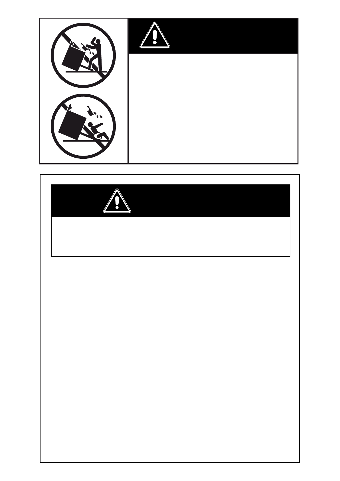
WARNING !
To reduce the risk of tipping the appliance,
the appliance must be secured by properly
installed anti-tip device packed with the
appliance.
• ALL RANGES CAN TIP
• INJURY TO PERSONS COULD RESULT
• INSTALL ANTI-TIP DEVICE PACKED
WITH RANGE
• SEE INSTALLATION INSTRUCTIONS
–Do not store or use gasoline or other ammable vapors and
liquids in the vicinity of this or any other appliance.
–NEVER use this appliance as a space heater to heat or warm
the room. Doing so may result in carbon monoxide poiso-
ning and overheating of the appliance.
–WHAT TO DO IF YOU SMELL GAS:
• Do not try to light any appliance.
• Do not touch any electrical switch.
• Do not use any phone in your building.
• lmmediately call your gas supplier from a neighbor’s
phone. Follow the gas supplier’s instructions.
• lf you cannot reach your gas supplier, call the re depart-
ment.
–Installation and service must be performed by a qualied
installer, service agency, or the gas supplier.
If the information in this manual is not followed exactly,
a re or explosion may result causing property damage,
personal injury, or death.
WARNING !

3
Thisapplianceisdesignedandmanufacturedsolelyforthecookingofdomestic(household)food
andinnotsuitableforanynonedomesticapplicationandthereforeshouldnotbeusedinacom-
mercialenvironmement.
Theappliancewarrantywillbevoidiftheapplianceisusedwithinanonedomesticenvironmement
i.e.asemicommercial,commercialorcommunalenvironment.
CONVERSIONLABEL
DATAPLATE

4
INSTALLATION INSTRUCTIONS
WARNING!
THIS APPLIANCE MUST BE INSTALLED BY A QUALIFIED INSTALLER.
Improper installation, adjustment, alteration, services, or maintenance can cause injury or property damage. Consult a quali-
ed installer, service agent, or the gas supplier.
Screwdriver 2 - Wrench
T-handle
wrench
Tape
measurePencil
Adjustable
pliers
Adjustable
wrench
Suitable protective
gloves Drill
Hammer
TOOLS NEEDED FOR INSTALLATION (NOT SUPPLIED WITH THE APPLIANCE)
IMPORTANT: The use of suitable protective clothing/gloves is
recommended when handling, installing of this appliance.

5
GENERAL INFORMATION
1. Installationmustconformwithlocalcodesor,intheabsenceof
localcodes,withtheNational Fuel Gas Code,ANSIZ223.1-
LatestEdition,CAN/CGA-B149.1orCAN/CGA-B149.2.
2. Installationinmanufactured(mobile)home:installationmust
conform with the Manufactured Home Construction and
Safety Standard, Title 24 CFR, Part 3280 [formerly the Fe-
deral Standard for Mobile Home Construction and Safety,
Title 24, HUD (Part 280)]or,whensuchstandardisnotappli-
cable,theStandardforManufactured Home Installations,
ANSI/NCSBCS A225.1, or with local codes where applica-
ble.
3. Installation in Recreational Park Trailers: installation must
conformwithstateorothercodesor,intheabsenceofsuch
codes, with the Standard for Recreational Park Trailers,
ANSI A119.5.
4. WARNING!!
This appliance shall not be used for space heating. This
information is based on safety considerations.
5. AlIopeningsinthewallbehindtheapplianceandintheoor
undertheapplianceshallbesealed.
6. Keepapplianceareaclearandfreefromcombustiblemate-
rials,gasoline,andotherammablevapors.
7. Donotobstructtheowofcombustionandventilationair.
8. Disconnecttheelectricalsupplytotheappliancebeforeser-
vicing.
9. Whenremovingapplianceforcleaningand/orservice;
A. Shutoffgasatmainsupply.
B. DisconnectACpowersupply.
C. Disconnectgaslinetotheinletpipe.
D. Carefullyremovetherangebypullingoutward.
CAUTION:Rangeisheavy;usecareinhandling.
10. Electrical Requirement
Electrical installation should comply with national and local
codes.
11. Air Supply and Ventilation
Theinstallermustreferstolocal/nationalcodes.
12. Gas Manifold Pressure
Naturalgas-4.0”W.C.P.
LP/Propane-11.0”W.C.P.
13. Themisuseofovendoor(e.g.stepping,sitting,orleaningon
them)canresultinpotentialhazardsand/orinjuries.
14. Wheninstallingorremovingtherangeforservice,arollinglift
jackshouldbeused.Donotpushagainstanyoftheedgesof
therangeinanattempttoslideitintooroutoftheinstallation.
Pushingorpullingarange(ratherthanusingaliftjack)also
increases the possibility of bending the leg spindles or the
internalcouplingconnectors.
WARNING!!
ELECTRICAL GROUNDING INSTRUCTIONS
The range must be electrically grounded in accordance with
local codes or, in the absence of local codes, with the Natio-
nal Electrical Code, ANSI/NFPA No. 70-latest edition, in Cana-
da Canadian Electrical Code.
Installation should be made by a Iicensed electrician.
FOR PERSONAL SAFETY, THIS APPLIANCE MUST BE PRO-
PERLY GROUNDED.
Ifanexternalelectricalsourceisutilized,theinstallationmustbe
electrically grounded in accordance with local codes or, in the
absenceof localcodes,withthe national ElectricalCode,ANSI/
NFPA70.
REPLACEMENT PARTS
Onlyauthorizedreplacementpartsmaybeusedinperformingser-
viceontherange.Replacementpartsareavailablefromfactory
authorizedpartsdistributors.Contactthenearestpartsdistributor
inyourarea.

6
PROXIMITY TO SIDE CABINETS
1. Thisrangemaybeinstalleddirectlyadjacenttoexisting36”(914mm)
highbasecabinets.
Rangedimensions:
• width:29”7/8(759mm)
• depth:24”13/64(614.9mm)
• height (without backguard): MIN 35” 21/32 (905.5 mm) - MAX 36”
11/32(923mm)
• backguard(height):3”(76mm)
Gas line opening: Wall-37/64”(14.5mm)fromtherightsidetocentre
ofrange;from5”7/16(138mm)to6”1/8(155.5mm)[dependingonfeet
regulation]fromtheoor.
Grounded outlet:shouldbelocated37/64”(14.5mm)fromtheleftside
tocentreofrange;from5”7/16(138mm)to6”1/8(155.5mm)[depen-
dingonfeetregulation]fromtheoor.
2. TherangeCANNOTbeinstalleddirectlyadjacenttosidewalls,tallcabi-
nets,tallappliances,orothersideverticalsurfacesabove36”(914mm)
high.
Theremustbeaminimumof11”13/16(300mm)sideclearancefromthe
rangetosuchcombustiblesurfacesTOTHELEFTorTOTHERIGHT
abovethe36”(914mm)highcountertop.
IMPORTANT: One side (left or right) above the 36” (914 mm) high
countertop must always be kept clear.
Island installation: Theremustbeaminimumof12”(305mm)clearan-
cefrom therearof thebackguardtosuch combustiblesurfaceon the
backoftherangeabovethe36”(914mm)highcountertop.
3. Themaximumuppercabinetdepthrecommendedis13”(330mm).Wall
cabinetabovetherangemustbeaminimumof30”(762mm)abovethe
countertopforawidthofminimum30”(762mm):ithastobecentered
withtherange.Sidewallcabinetsabovetherangemustbeaminimum
of18”(457mm)abovethecountertop.
installation
1
Fig. 1.1
3”
(76mm)
MIN35”21/32(905.5mm)
MAX36”11/32(923mm)
24”13/64
(614.9mm)
29”7/8
(759mm)

7
AA
B
ASSEMBLING THE BACKGUARD
It is mandatory to install the backguard.
Assemblethebackguardasshowningure1.3:
• Screwthe2screws“A”interposingthespacers.
• Screwthecentralscrew“B”.
1
Fig. 1.3
GAS AND ELECTRIC CONNECTION
Fig. 1.2
Dottedlineshowingtheposition
oftherangewheninstalled
Areafor
ELECTRICAL
connection
Areafor
GASconnection
B
A
B
C
C
Ref. inch mm
A5”7/16-6”1/8 138-155.5
B14”3/8 365
C37/64” 14.5
(*):Dependingonfeetregulation

8
B
G
E
D
C
F
A
A
B
C
E
D
F
G
A
A
PROXIMITY TO SIDE CABINETS
STANDARD INSTALLATION
Fig. 1.4b
Fig. 1.4a
OVEN VENT
Ref. inch mm
A0” 0
B36” 914
C11”13/16 300
D30”minimum 762minimum
E18”minimum 457minimum
F13”maximum 330maximum
G20”minimum 500minimum
OVEN VENT
1

9
PROXIMITY TO SIDE CABINETS
ISLAND INSTALLATION
A
A
B
G
E
D
F
C
H
A
A
B
G
E
D
F
C
H
Fig. 1.5b
Fig. 1.5a
OVEN VENT
Ref. inch mm
A0” 0
B36” 914
C11”13/16 300
D30”minimum 762minimum
E18”minimum 457minimum
F13”maximum 330maximum
G20”minimum 500minimum
H12”minimum 305minimum
OVEN VENT
1

10
1
YOU MUST USE STABILITY
ANTI TIP BRACKET TO
PREVENT UNIT FROM
TIPPING.
ANTI-TIP STABILITY DEVICE INSTALLATION INSTRUCTIONS
1. Theanti-tipbrackethastobeattachedasshownongurebelow(onlyrearleftside),
ithastobexedontheoorandontherearwallbyno.6(six)suitablescrews(not
supplied).
2. Afterxingtheanti-tipbracket,sliderangeintoplace.Besuretherearleftfootslides
undertheanti-tipbracketattached.
LEVELLING THE RANGE
Therangeisequippedwith4LEVELLINGFEETandmaybelevelledbyscrewingor
unscrewingthefeet(gs.1.6-1.7).
Itisimportanttoobservethedirectionsofgures1.6,1.8a,1.8b.
Fig. 1.8bFig. 1.8a
Fig. 1.7
Fig. 1.6
Suppliedwiththerange
inaseparatekit
Suppliedwiththerange
inaseparatekit
0”
0mm
+5/16”
+8mm
+5/16”
+8mm
+11/16”
+17.5mm
Fig. 1.9
Dotted line showing the position
oftherangewheninstalled
ANTI-TIPSTABILITY
DEVICEFIXING
Anti-tipstability
device Rearleft
feetofrange
3”15/64
(82mm)
Other manuals for VEFSGE304P
1
Table of contents


