VeEX OX-MPO-12 Specification sheet

TECHNICAL NOTE
OX-MPO-12 Switch Reference Card
Evaluating MPO-SM Connectors with FX150+ OTDRs (other OTDRs TBD)
Month 2020 | D08-00-XXX Rev. XXX ©2020 VeEX Inc. All rights reserved.www.veexinc.com
This quick guide provides setup instructions to perform MPO OTDR fiber testing using an FX150+/FX150 OTDR and VeEX
OX-MPO-12 Switch. It is assumed that the user is familiar with VeEX OTDR setup and trace analysis functions discussed in
the OTDR series manual.
Setup Materials:
Description
Quantity
Notes:
FX150+/FX150 OTDR
1x
Needs Latest GA release software (1.00.4912 or up). See About Page to check.
OX-MPO-12 Switch
1x
No comment
Micro-USB (B) to Micro-USB (B)
1x
Provided with purchase of OX-MPO-12 Switch, required for FX150+/FX150
OTDR to control OX-MPO-12 Switch
SC/APC - SC/APC (1m) patch cord
1x
Connection transforms a simplex OTDR port into multifiber OTDR.
OX-MPO-12 Test Cable Kit
1x
Upon price quote/purchase option
MPO launch and receive cables
1x launch,
1x receive
User-supplied, if OX-MPO-12 Test Cable Kit was not purchased.
Figure 1: Test Setup Combinations (not all shown)
General Setup Instructions: (Steps 1 to 4, refer to Figure 1)
1. After gathering all required materials mentioned in the table, boot up the FX150/FX150+ OTDR. If FX150/FX150+ is
already booted up with OTDR application open and MPO switch is disconnected, exit out of the active application
to Home menu. (Figure 1)
2. Connect one end of the Micro-USB (B) to Micro-USB (B) cable from the FX150/FX150+ OTDR port to the OX-MPO-
12 Switch port.
3. Attach one end of the 1 m
SC-APC to SC-APC simplex patch cord
from the OTDR port (SC-APC) to the SC-APC port
of the switch.
4. Attach either one of three cases to the MPO output port of the OX-MPO-12 Switch
a. MPO/APC to MPO/UPC hybrid cable for launch cable, and MPO/UPC cables for FUT (Fiber under test) and
receive cable. Alternately, another MPO/APC to MPO/UPC hybrid cable can be used at the receive end.
b. MPO/APC ends for launch cable, FUT, and receive cable.
TECHNICAL NOTE: Title Page | 2
c. MPO/APC to simplex cable fanout 2x (SC-APC, SC-UPC, FC-APC, FC-UPC, LC-APC, LC-UPC…) and FUT.
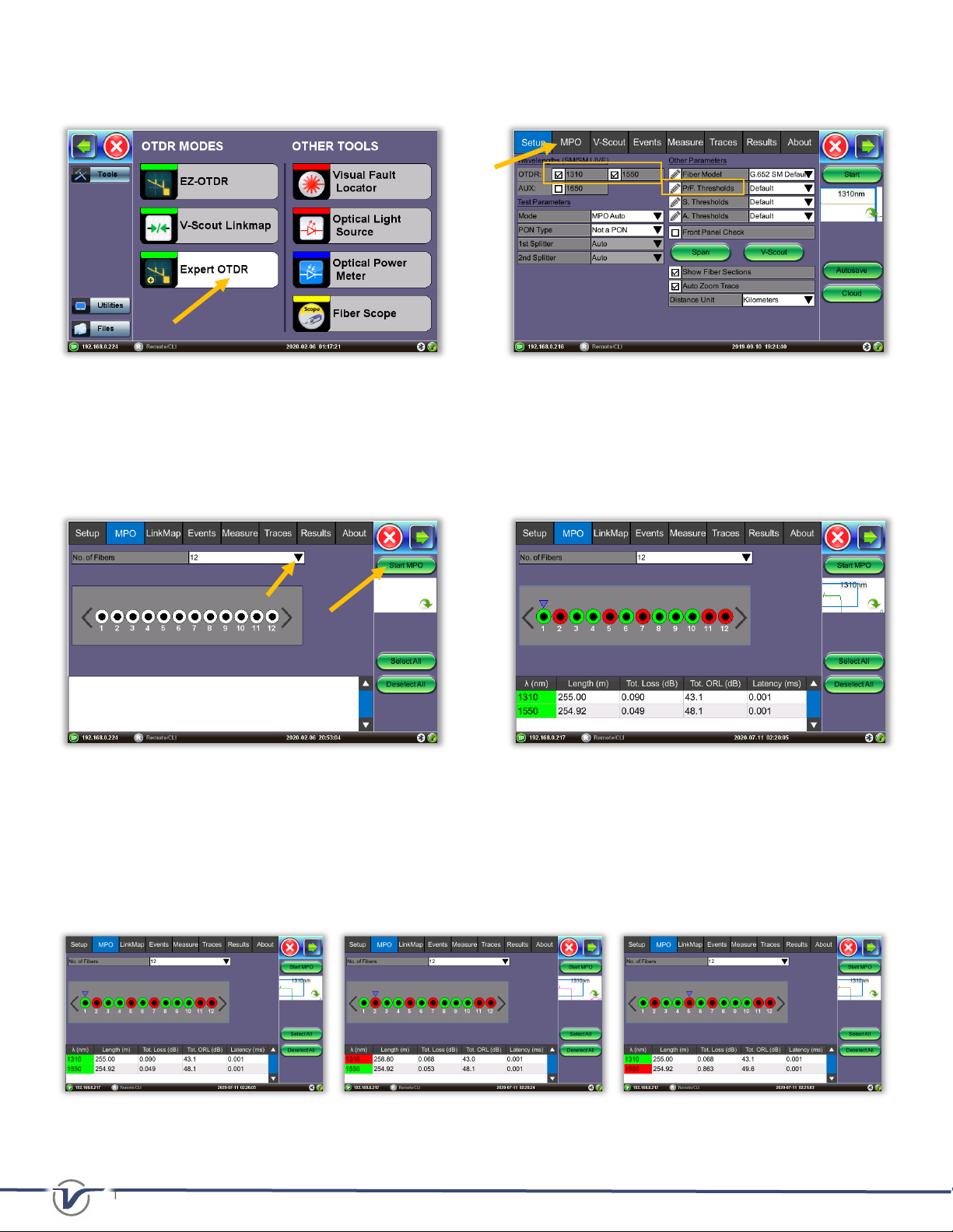
5. On the OTDR’s Home Menu Screen, select the Expert OTDR tab. (Figure 2)
Figure 2: FX150/150+ OTDR Home Menu Figure 3: Setup Parameter Menu
6. Select wavelengths to test (1310 and 1550 nm supported only). Navigate to the MPO Tab when the Expert OTDR
application loads. Users can also select MPO Auto in Mode under Test Parameters and Start to test all MPO fibers.
7. Choose from the dropdown menu the MPO connector fiber count (8 or 12). Select what individual/all fibers to test
from the MPO control. Press Start MPO to run test. If no fibers are selected, the user is prompted to select at least
one fiber to run a test.
Figure 4: MPO fiber initial selection – Run All Figure 5: MPO Pass/Fail Results Screen
8. Tap the stylus on the left <and right >arrow keys to move the cursor to view each individual MPO fiber test results
(1 to 12). This will change the MPO fiber number results viewed on Linkmap, Events, and Measure Tab. The colored
outer rings and colored boxes are pass and fail markers to indicate an event on a trace has passed or failed based
on P/F Thresholds criteria defined from the Setup parameters. View the Linkmap Tab or Events Tab for full
information.
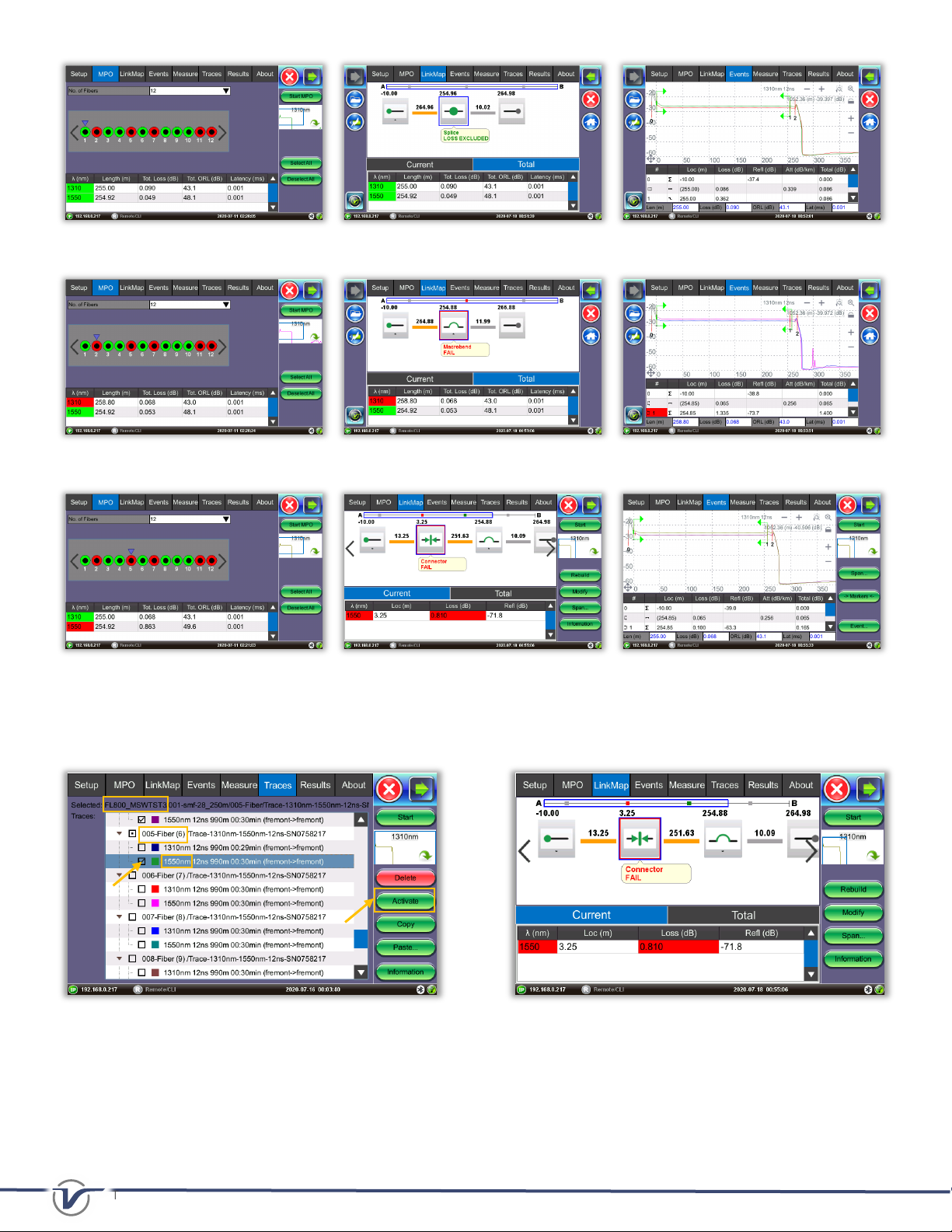
Figure 6 – Moving the blue cursor to view OTDR measurements per individual fiber
TECHNICAL NOTE: Title Page | 3
Figure 7– MPO1 results-> View Linkmap and Events table
Figure 8– MPO2 results-> View Linkmap and Events table
Figure 9– MPO5 results-> View Linkmap and Events table
9. To see trace, LinkMap, Event results filtered for a specific wavelength, use the Traces Tab and search for the
corresponding “JobName”->MPO fiber->test wavelength.” Select Activate. (Figure 10)
Figure 10: Traces Tab – Viewing specific traces to Figure 11: LinkMap Tab – Connector failed Loss P/F threshold
troubleshoot the link.
10. The following results were autosaved, but the user can manually save results by pressing Save… in the Results Tab
Menu. (Figure 13) The MPO results are grouped under one CableID, 001-smf-28_250m, shown below. Users can
upload measurement results to Fiberizer™ Cloud or into USB storage through USB export button.

TECHNICAL NOTE: Title Page | 4
*Make sure that a Fiberizer Cloud account has been linked/entered in
Cloud
button in the
Setup Tab
(Figure 14)
to upload
results.
Figure 12: Events trace view Figure 13: Results Tab Menu with 12 traces (seven shown)
Figure 14: Results are synced with Fiberizer Cloud Account.
Figure 15: Example Test Setup Used
About VeEX
VeEX Inc., a customer-oriented communications Test and Measurement company, develops innovative test and monitoring
solutions for next generation telecommunication networks and services. With a blend of advanced technologies and vast
technical expertise, VeEX products address all stages of network deployment, maintenance, field service turn-up, and
integrate service verification features across Copper, Fiber Optics, CATV/DOCSIS, Mobile 4G/5G backhaul and fronthaul,
next generation Transport Network, Fibre Channel, Carrier & Metro Ethernet technologies, WLAN and Synchronization.
2827 Lakeview Court, Fremont, CA 94538, USA | Tel.: +1 (510) 651-0500 | Fax: +1 (510) 651-0505 | [email protected] | www.veexinc.com
Table of contents
Other VeEX Switch manuals


