VDO AcquaLink User manual

AcquaLink 110mm Gauges
Installation Instructions
V1.1 08/16

2

Content
Preliminary Remarks 4
Safety Instructions 4
Safety Instructions for Maintenance 6
The VDO 110mm Gauge 7
Components 7
VDO Bus 8
Available versions 8
The NMEA Interface 10
Installation of the VDO 110mm gauge 13
Hardware Specication 16
Pinout 17
Technical Data 18
Accessory 19
3
AcquaLink 110mm Gauges
Preliminary Remarks
In purchasing a 110mm gauge from the VDO AcquaLink marine range you
have decided on a high value product, which has been manufactured
according to acknowledged technical standards. Modern production processes
and compliance with currently applicable quality assurance standards
guarantee that our products leave the factory in perfect condition.
We thank you for making a good choice, and we are convinced that this
instrument will be reliable and a great help to you and keep you safe at sea.
In order to ensure easy and safe handling of your VDO 110mm gauge, you
should familiarize yourself with all the features and functions.
Please take the time to read these instructions carefully and completely.
Safety Instructions
Installation
This product has been developed, manufactured and tested in accordance
with the requirements of EC and UL directives and the acknowledged state of
the art.
Please follow all the instructions given in this handbook exactly.
Please pay attention to all text passages labeled with this
symbol. These are very important hints for operating and
security of the instruments.
4
Before beginning work the negative Terminal of
the battery should be disconnected.
Use of information provided by the VDO 110mm gauge does not release
you from the responsibility over your ship and demands good
seamanship. Always use your nautical experience in interpreting the
displayed values.
If you carry out this work yourself, wear suitable working clothes. Do not
wear wide fitting clothes. If you have long hair, wear a hair-net. Clothes
and hair can get caught in moving and rotating parts.
Wearing of metallic or conductive jewellery, such as necklaces, bracelets,
rings etc. is not allowed when working on the electrical installation on
board.
Please note that with disconnection of the battery, all volatile electronic
memories lose their input values and must be reprogrammed.
Explosion hazard! Before beginning work on
the engine compartment of petrol engines,
switch on the ventilator of the engine
compartment.
Ensure that necessary clearance is provided behind the cable opening, at
the position where the gauge is to be installed.
When selecting the installation position for the gauge, take care that no
stringers are drilled. Be careful also of furniture, floorboards,
superstructure boxes, cables etc.
When carrying out installation work with a sealing compound, solvent
vapours can be formed. Make sure of adequate ventilation and follow the
instructions for use of the sealing compound manufacturer.
5

For the installation only use VDO or NMEA approved cables.
If you don’t use standard cables, the wires used should be adequately
insulated or should have sufficient electrical strength, and the contact point
should be protected against electrical shock hazard. The electrical conducting
components of the connected consuming devices should also be protected
against direct contact through suitable measures. Installation of bare metallic
wires and contacts is not allowed.
Take account of the wire cross section. A reduction of the wire cross section
results in a higher current density. This can cause the wire to heat up and
potentially cause fire.
Connect the wires only in accordance with the wiring diagram.
Safety Instructions for Maintenance
The 110mm gauge is maintenance-free. Do not use cleaning agents.
Repairs on the gauge should be carried out only by VDO authorized
specialists
6
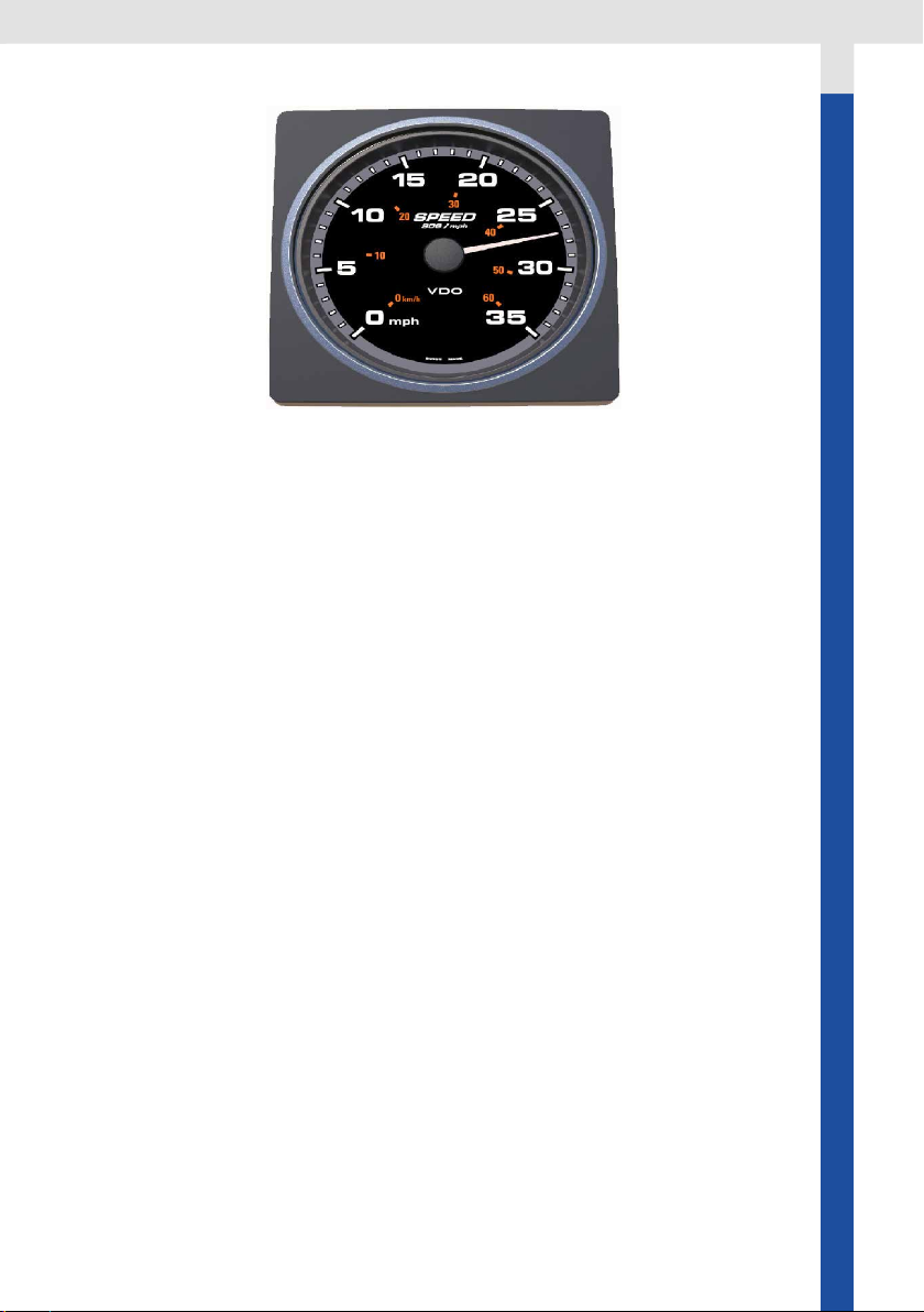
The VDO 110mm Gauge
The 110mm gauges can be used in the AcquaLink system or added to a
existing NMEA 2000 network. In the AcquaLink system the gauges
receive the data through the AcquaLink Nav Box. The gauges are daisy
chained with VDO bus cables. Please refer to chapter “VDO Bus” and
follow the installation rules and limitations.
When used in a NMEA 2000 system the gauges can display data present
in the NMEA 2000 network. Please refer to the chapter “NMEA 2000” and
follow the installation rules and limitations.
Components
In the box:
- 110mm gauge
- Square bezel
- Gasket
- Spinlock
- Silicone protection cover
- Installation instruction
- Mounting template
7
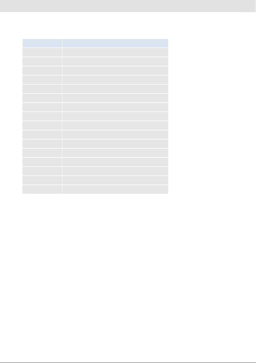
Available versions
A2C Number Function
A2C59501900 Apparent wind angle gauge
A2C59501901 Apparent wind angle magnied gauge
A2C59501902 Apparent wind speed gauge
A2C59501903 Depth gauge 200m / 660 ft
A2C59501904 Depth gauge 660 ft / 200m
A2C59501905 Speed through water 12 knots
A2C59501906 Speed through water 50 knots
A2C59501907 Speed through water 35 mph / 60 kmh
A2C59501908 Speed over ground 12 knots
A2C59501909 Speed over ground 70 mph / 115 kmh
A2C59501910 Speed over ground 35 mph / 60 kmh
A2C59501911 Compass
A2C59501912 Rudder angle gauge 110 mm
A2C59501913 Tachometer 3000 rpm
A2C59501914 Tachometer 5000 rpm
A2C59501915 Tachometer 7000 rpm
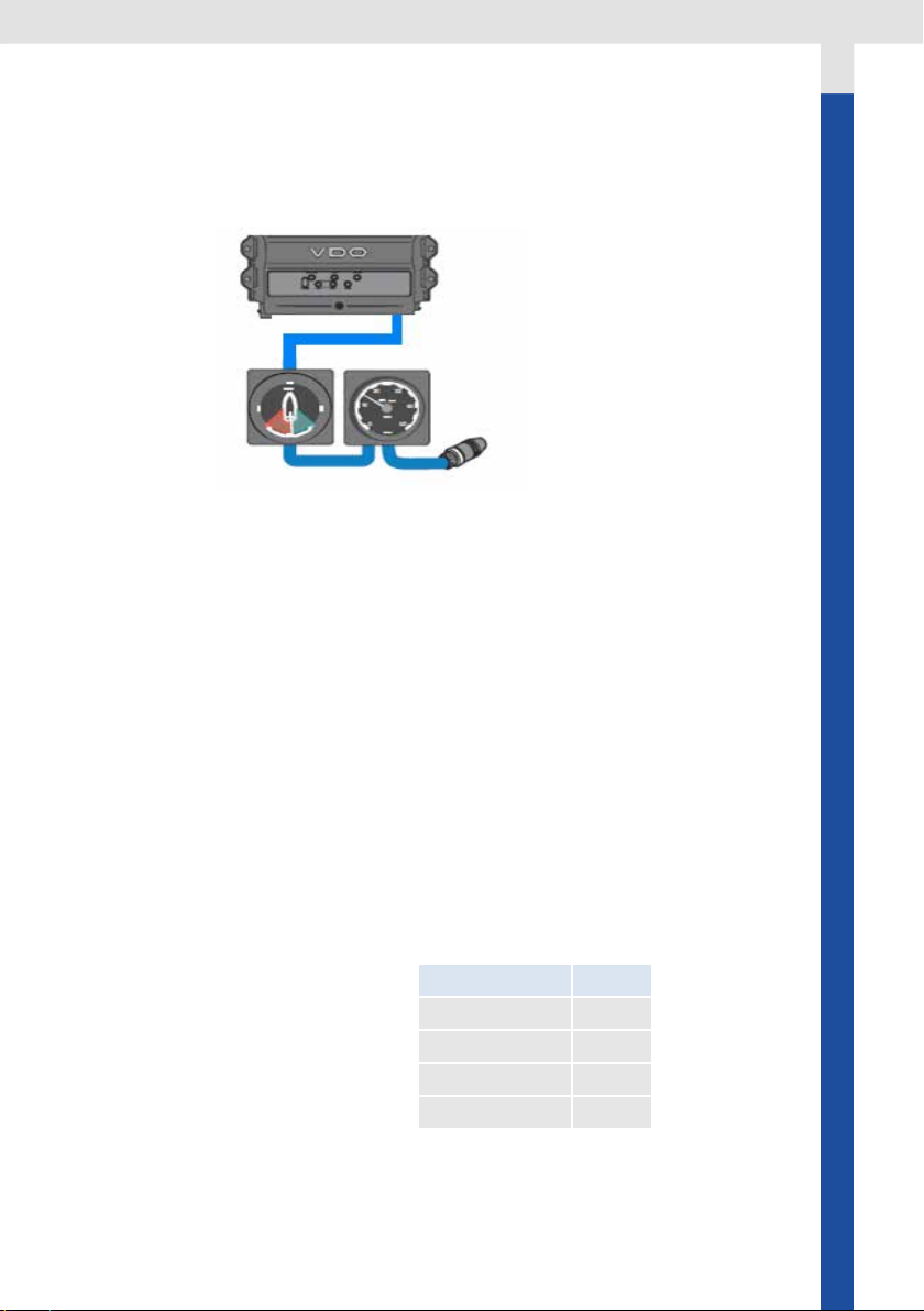
VDO Bus
The VDO Bus is a proprietary CanBus system based on NMEA 2000. Heart of
the VDO Bus AcquaLink system is the Nav Box. The Nav Box provides a wide
range of digital and analogue input possiblities and distributes the received
data to all gauges in the VDO Bus network. The VDO Bus uses M12 8 Pin
cables and all devices are powered through the network.
The Nav Box has three VDO Bus ports, so three seperate VDO Bus segments
can be installed. This helps to reduce the power drop in the system and allows
an easy installation in all areas of the vessel.
Every 110mm gauge has two equal VDO Bus connectors in the rear.
8
Important:
The VDO Bus network has to be terminated with three 120ohm termina-
tors (included with the Nav Box)
You need to connect an 180Ohm terminator plug at the end of any VDO
segment or not used Nav Box connector.
Note:
VDO Bus cables have two female connectors. In order to extent the cable
length an optional gender changer connector is needed (A2C38805500)
VDO Bus Limitations
The Nav Box provides power to all the 110mm gauges and 4.3’’ TFTs con-
nected to the system. Due to the power consumption and the resistance of
the cables there are limitations of the maximum cable length and number
of possible instruments in the system.
In order to have a properly working system the voltage drop of every of the
three VDO Bus segments have to be calculated.
The load equivalency number (LEN) for the 110mm gauge is 4.
1 LEN = 0.05 Ampere
LEN List for VDO Products:
Product LEN
Nav Control 4
110mm gauge 4
4.3’’ TFT 12
52mm gauge 2
9

The NMEA Interface
The VDO 110mm gauges can be directly connected to a NMEA 2000 network
without using the Nav Box system.
Note: If using the gauges with NMEA 2000 following limitations have to
be exepted:
- The gauges are not NMEA 2000 certied but compatible
- The illumination of the gauges is always ON
- As soon as the NMEA 2000 power is switched off the indication
pointer will go back to the zero position
-The gauges will only read the NMEA 2000 PGNs listed below. No
calibration is possible through the gauges
- When data is available from multiple sources, the gauge
automatically selects the source with the lowest instance number
Please follow the general NMEA 2000 installation rules you can nd at
www.nmea.org.
Calculation
12V power supply:
The voltage drop for every segment of the VDO Bus is calculated as follow:
Ohm‘s Law: E (voltage drop) = I (circuit current) x R (wire resistance)
R= 2/2x Cable Length (m) x Power Pair Resistance / 100
I= LEN (Load Equivalency Number) x 0.050 amps
L=Total length of VDO Bus cables on one segment
→ E = 0.05 x LEN x L x 0.057
The voltage drop for each VDO Bus Segment shouldn’t be higher than 3V
Note: VDO BUS has 2x AWG 22 Power/Ground cables →different voltage
drop calculation than NMEA 2000
24V power supply:
If using a 24V system the voltage drop may not be higher than 9V
10
Other manuals for AcquaLink
1
Table of contents
Other VDO Marine Equipment manuals


Popular Marine Equipment manuals by other brands


Clarion
Clarion GR10BT Owner's manual & installation manual

Raymarine
Raymarine Maxiview ST80 Owner's handbook

GUIDANCE MARINE
GUIDANCE MARINE 20- Series Installer's guide

Raymarine
Raymarine ST60 Tridata Owner's handbook

olympia electronics
olympia electronics ΒS-531/1/MAR quick start guide

Sonic
Sonic 2024 Operation manual