Vaillant VER 75/3 User manual
Vaillant-Witte®Elektro-Raumheizer
Vaillant-Witte®Independent Room Heaters
VER 75/3, VER 100/3, VER 150/3, VER 200/3, VER 250/3
INSTALLATIONS- UND BEDIENUNGSANLEITUNG
INSTALLATION AND OPERATING INSTRUCTIONS
Typ Art.-No. Connected load Voltage
[kW] [V]
VER 75/3 6205 0,75
VER 100/3 6206 1,00 1/N/
VER 150/3 6207 1,50 PE~
VER 200/3 6208 2,00 230
VER 250/3 6209 2,50
8
Contents page
1 Application 8
2 Construction 9
3 Installation 10
4 Electrical connection 11
5 Starting up 11
Technical data 12
Tabelle 1.1 Typenübersicht
Please read carefully through all the
information given in this manual.
It provides important instruction for
the installation and maintenance of
the appliance.
After installing the heater,please hand
these instructions as well as the opera-
ting instruction to the user for safe
keeping.
Installation and initial start-up only by
a qualified contractor.
Guarantee will only be valid if the
appliance has been installed and
started up initially by an approved
contractor, who is responsible for the
observance of applicable standards
and installation instructions. We do
not accept responsability for damage
arising from the non-observance of
these instruction.
1 Application
Universal independant room heaters,
wallvanvectorsVER75/3-VER250/3,
are designed and manufactured for a
wide range of applications: residenti-
al and business premises, bathrooms,
halls, landings etc.
The VER 100 - 250/3applianceshave
a splash-prof enclosure.
V-W 139/0
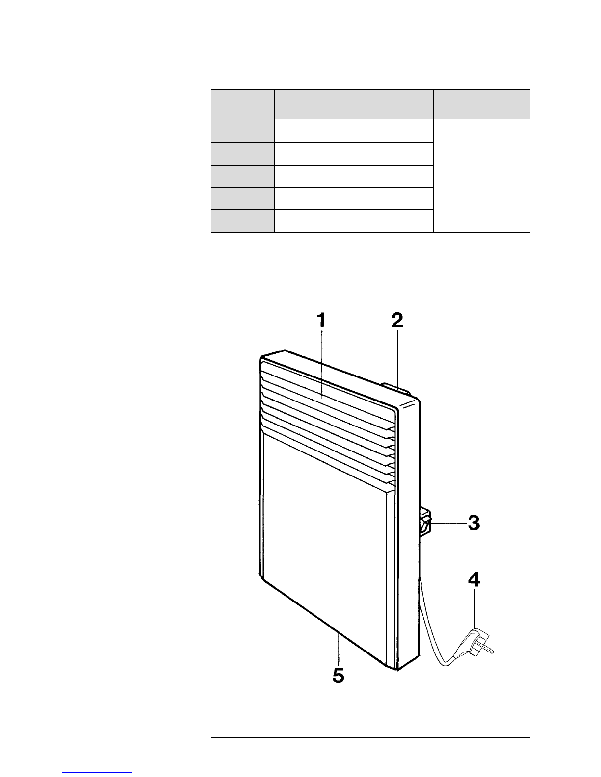
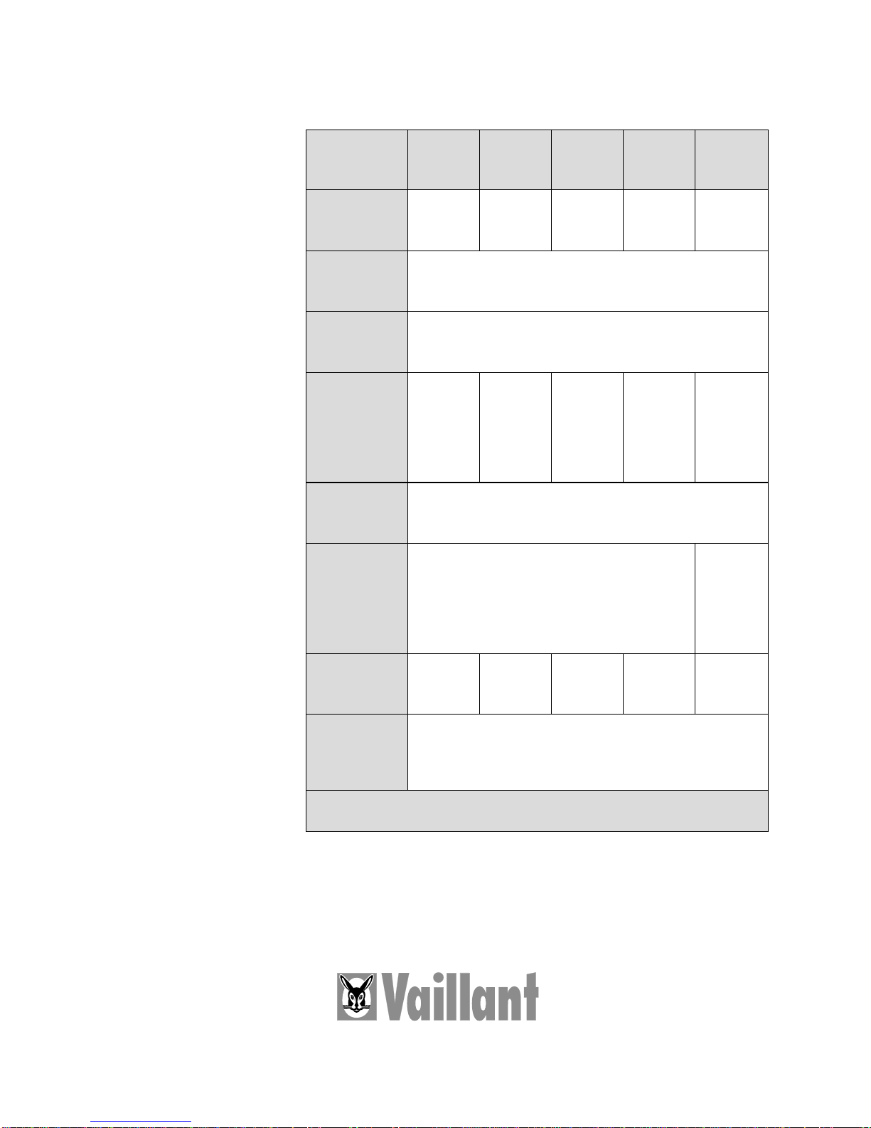
Fig. 2.1 Construction VER 75/3
Legend to fig. 2.1
1 Air outlet grille
2 Thermostat
3 Switch
4 1 m connecting lead up to
75/3 ... VER 200/3 with Euro-standard elbow plug
5 Air inlet grille
9
2 Construction
(Fig. 2.1, page 8)
The housing which accommodates the
special-purpose heating unit is provi-
ded with air slots underneath and at
the front. The air is heated by free
convection without a fan.
The cold air enters the appliance on
the underside, is heated as it flows
past the special heating element and
leaves the heater through the air outlet
grille.
At the rear, the convector is fitted with
a thermostat on which the temperature
can be infinitely selected with a dial.
Please note
•The room heater must not be
installed underneath a wall socket
outlet.
•The room heater must not be
permanently wired to the mains.
•The appliance must be installed in
the bathroom in such a way that
switches, regulating and control
elements cannot be touched by a
person using the bath or the
shower.
•Important! The housing temperature
exceeds 60 °C. There is a danger
of fire. See warning notice on the
appliance.
•Never cover the heater; not even
for a short time!
•There is a danger of fire. See
warning notice on the appliance.
•Never mount the appliance directly
next to a curtain, screens or similar
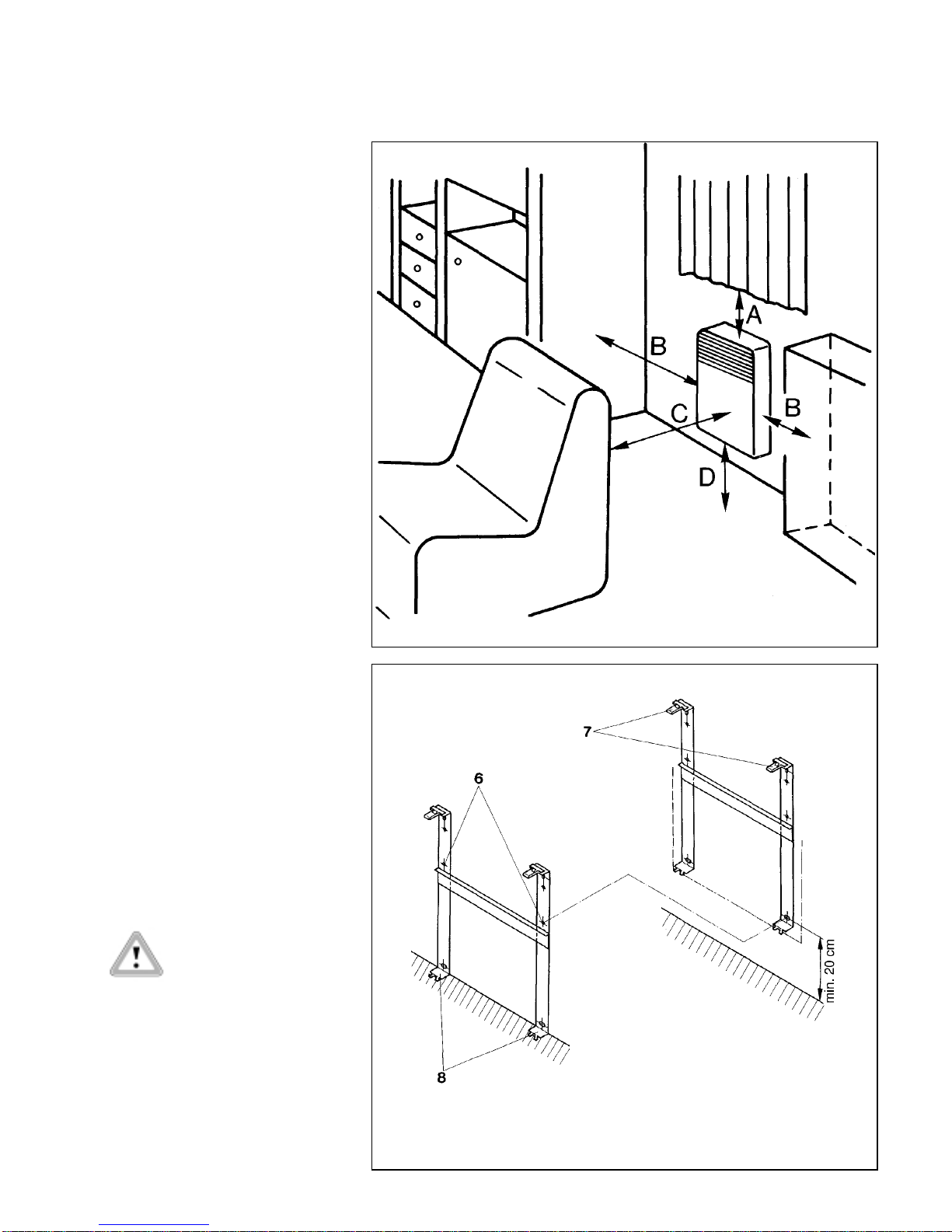
(see fig. 2.2).
V-W 108/0
Fig. 2.2 Wall mounting
V-W 142/0 X
Fig. 3.1 Appliance bracket
6 bracket
7 fixing clips
8 hooking tab
A =
> 10 cm
B =
> 10 cm
C =
> 75 cm
D =
> 20 cm
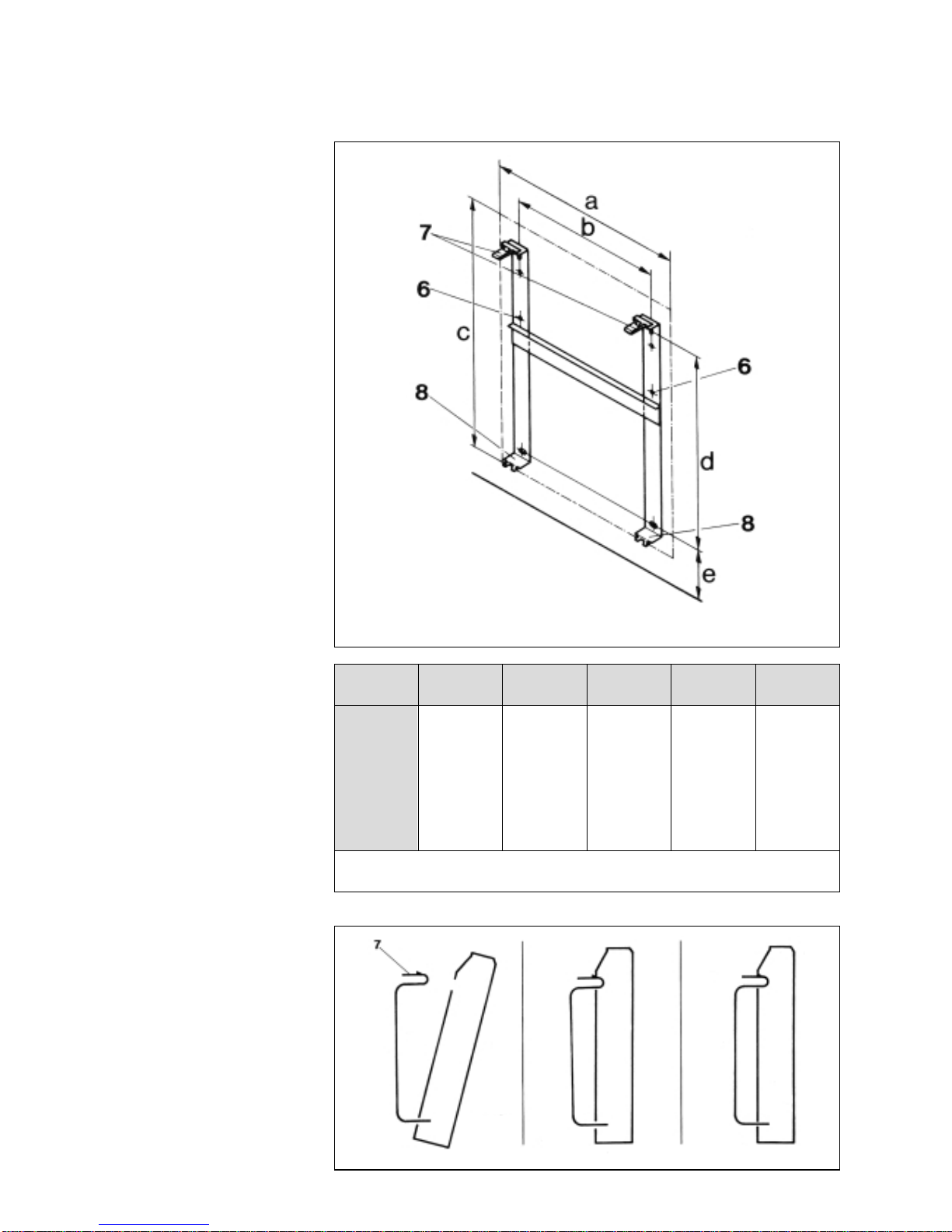
Appliance a b c d e
type
VER 75/3 340 84 430 289 > 200
VER 100/3 420 164 430 289 > 200
VER 150/3 580 324 430 289 > 200
VER 200/3 740 484 430 289 > 200
VER 250/3 900 564 430 289 > 200
Distance from wall with appliance bracket 20 mm
10
V-W 106/1
Fig. 3.2 Fixing
V-W 143/0
Fig. 3.3 Mounting
6 bracket
7 fixing clips
8 hooking tab
•If the heater is left off for a lengthy
period or when cleaning it, switch
it off with the switch (3, fig. 2.1,
page 8) on the side.
•After the installation the line
connection has to be accessible.
•The installation and electrical
connection of the heater must be
carried out by an approved skilled
person.
3 Installation
Wall mounting
The heater must be mounted vertically
(see fig. 2.1, page 8).
Fix the appliance bracket to the wall
as shown in the installation sketch
(fig. 3.1 and 3.2), using the enclosed
installation materials. See fig. 3.1 on
page 9 for installation measurements.
It is essential to maintain the minimum
distance of 20 cm from the floor to the
lower fixing hole.
Hook the heater into the lower fixing
hooks.
Insert the upper fixing clips(7, fig.3.3)
in their positions and press in.
7 fixing clips
Tabelle 3.1 Distance
11
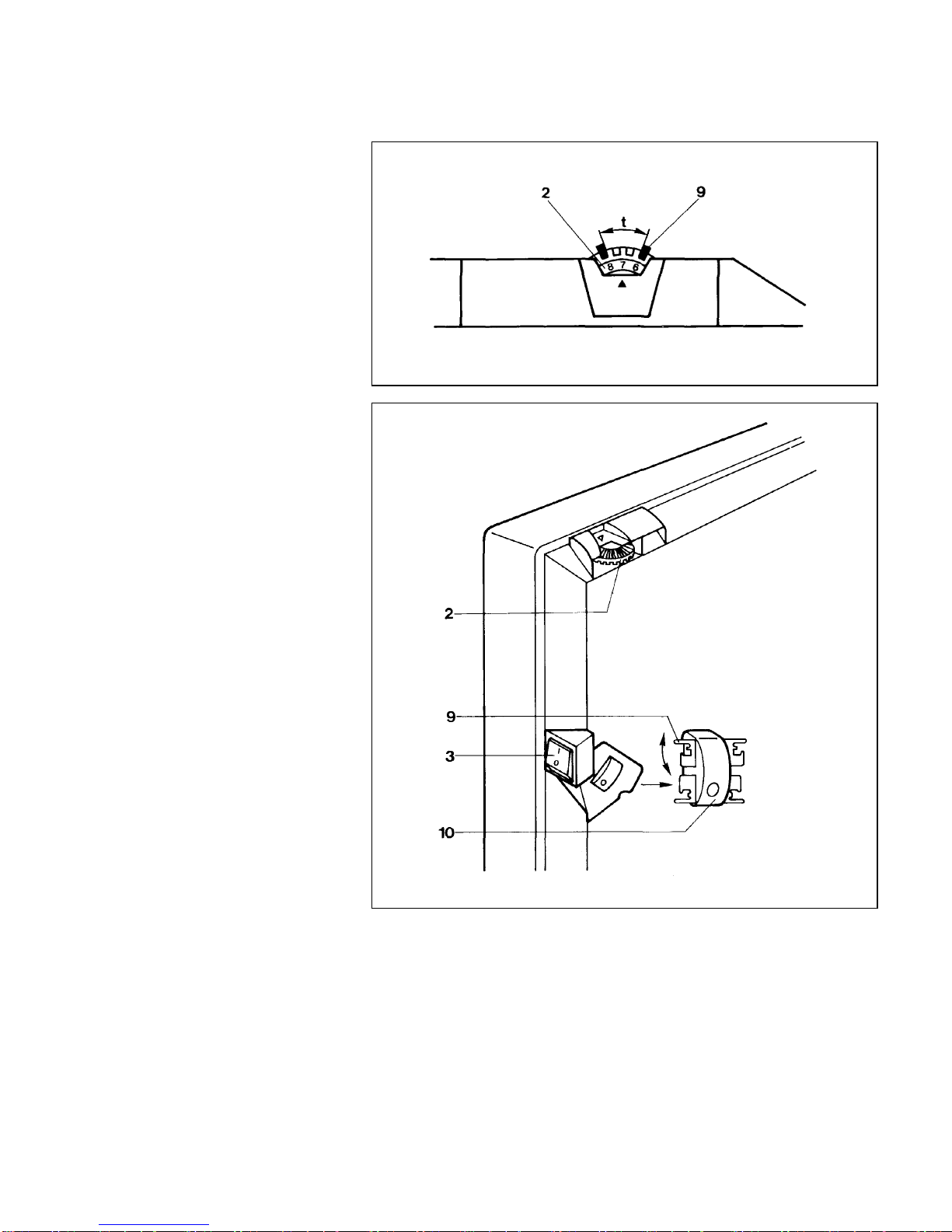
V-W 141/0
Fig. 5.1 Starting up
V-W 140/0
Fig. 5.2 Thermostat setting
4 Electrical connection
The appliance must be connected to a
230 V~ supply via the mains plug.
(For the VER 100/3 - VER 200/3).
A PE conductor is not present, since
the appliance is of the totally insulated
type.
The regulations of the local electricity
board must be observed.
The appliance must be installed so
that it can be disconnected from the
supply before any intervention (e. g.
pulling out the mains plug for VER
75/3 - VER 200/3).
The connecting lead is specific to con-
vectors.
Changing the connecting lead must
only be carried out by an approved
contractor.
Only use original Vaillant special-
purpose cables.
5 Starting up
Set the switch (3) to position „I”.
The built-in room thermostat keeps the
required room temperature constant.
If a room which is not being used is to
be protected against frost, set the ther-
mostat knob (2) to position (❄).
5.1 Switch (3)
The heater is switched off when the O
marking is visible. Involuntary control
is therefore impossible.
The frost protection safeguard is also
switched off at this setting.
5.2 Thermostat setting
Pull the two slides off the room ther-
mostat (fig. 5.1).
Fit the slides at both sides of the stop
according to the temperature/
temperature range.
Position ❄approx. 4 °C.
Position 7 approx. 20 °C.
Legend to fig. 5.1 and 5.2
2 Thermostat
3 Switch
9 Slide
10 Case
t Temperature setting range
Technische Daten
Für Schäden, die durch Nichtbeach-
tung dieser Anleitung entstehen, über-
nehmen wir keine Haftung.
Technical data
We do not accept responsability for
damage arising through the non-
observance of these installation
instruction.
8300 97 INT05 · 09/2000 V · Änderungen vorbehalten · Subject to alteration · Printed in Germany · Imprimé en Allemagne · Gedruckt auf 100 % Altpapier · Printed on 100% recycled paper
VaillantGmbH
BerghauserStraße40 .D-42850 Remscheid
Telefon(021 91) 18-0 .Telefax (0 21 91) 18-28 10
http://www.vaillant.de.E-Mail:[email protected]
Typ VER75/3 VER100/3 VER150/3 VER200/3 VER250/3
Art.-Nr. 6205 6206 6207 6208 6209
Anschlußwert 0,75 kW 1,00 kW 1,50 kW 2,00 kW 2,50 kW
connected load
Spannung 1/N/PE ~ 230 V
Voltage
Frostschutz ca. 4 °C
frost protection
Abmessungen:
Dimensions:
Höhe - height 430 mm 430 mm 430 mm 430 mm 430 mm
Breite - width 340 mm 420 mm 580 mm 740 mm 900 mm
Tiefe - depth 85 mm 85 mm 85 mm 85 mm 85 mm
Wandabstand 20 mm
dist. from wall
Anschlußkabel 1 m Anschlußkabel 1 m
mit Euro-Winkelstecker Anschluß-
kabel
Length of 1 m supply connection
connection lead via mains plug lead
Gewicht 3,2 kg 3,8 kg 4,9 kg 6,3 kg 7,3 kg
weight
Schutzart Spritzwasserschutz IP 24, Schutzklasse II
entspricht der Niederspannungs- und EMV-Richtlinie
type of enclose IP 24
Stand der Tabellenangaben: Juli 1995. Weiterentwicklung vorbehalten.
Data in this valid July 1995. Subject to chance in the course of further development.
This manual suits for next models
4
Table of contents
Popular Gas Heater manuals by other brands

Superior
Superior BGE18NV Installation and operation instructions

Dru
Dru Room-sealed atmospheric gas-fired heating... user manual

klover
klover TKR 35 user guide

Rothenberger Industrial
Rothenberger Industrial 035984 instruction manual

New Buck Corporation
New Buck Corporation 34 user manual

Hargrove
Hargrove Timberland Glow Operation and installation guide


Superior
Superior BGE18NR Operation instructions

Brant Radiant Heaters
Brant Radiant Heaters QTD Series User instruction

L.B. White
L.B. White Therma Grow HW220 Owner's manual and instructions

Sealey
Sealey LP35.V5 instructions

Italkero
Italkero Falo Evo User manual and assembly instructions

Desa
Desa 30LP owner's manual