UFO NOVA DMX User manual

Illuminator User Guide
Nova Illu inator Range
Models covered by this manual:
UFO NOVA DMX
UFO NOVA DMX-R
UFO NOVA DMX-T
UFO NOVA DMX-TR
Please read this manual fully before installin , operatin or performin
maintenance on the illuminator unit.
Issue 5 | Revised: 300517
Universal Fiber Optic Li htin LLC
6119A Clark Center Avenue | Sarasota | FL34238
Tel: 941-343-8115 or 800-UFO-5554
www.fiberopticli htin .com

Nova Illuminator Ran e
INTRODUCTION
Thank you for purchasin this UFO Illuminator.
Please read these instructions fully before connectin your unit to the
electrical supply, and keep them for future reference.
The UFO Nova ran e of illuminators are suitable for use with either lass or
PMMA fiber-optic harness
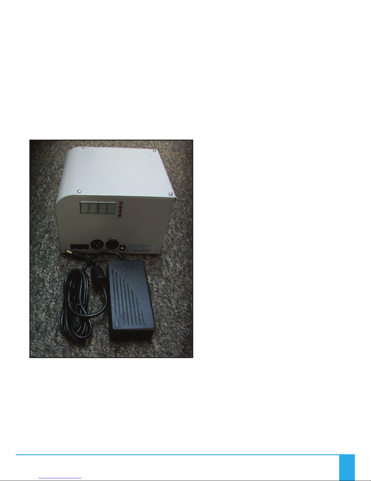
The Nova is powered by a 100-240 VAC remote desktop power supply unit.
IMPORTANT
THIS PRODUCT MUST BE INSTALLED IN ACCORDANCE WITH THE
APPLICABLE INSTALLATION CODE BY A PERSON FAMILIAR WITH THE
CONSTRUCTION AND OPERATION OF THE PRODUCT AND THE HAZARDS
INVOLVED.
THE LED ARRAY IN THIS ILLUMINATOR IS NOT REPLACEABLE. HEN IT
REACHES END OF LIFE THE HOLE UNIT MUST BE REPLACED.
2
Universal Fiber Optics 3
INSTALLATION INSTRUCTIONS
POWER SUPPLY REQUIREMENTS
The LED Illuminator is powered from a multifunction, multi-volta e, desk top
Power Supply Unit. Remove the 24V Desk Top PSU from its box. This PSU is an
IEC input device caterin for UK, European and USA mains supplies usin the
relevant power cord.

Nova Illuminator Ran e
4
CONNECTIONS
There are 3 connections required – the fiber port, the mains supply cable and
the DMX control cable. The fiber port should be connected first. Connect and
secure the fiber optic connector into the reen collar and secure usin the M5
lockin screw.
Connect the IEC power cord into the Desk Top PSU and plu the mains plu
into the electrical supply socket. Switch on power. The LED Indicator will
illuminate and the illuminator is ready for use. If no li ht is produced consult
the TROUBLESHOOTING section.
For DMX control connect up the DMX control cables to the XLR sockets on the
rear of the Illuminator. The pin out details for the plu s are shown below.
RJ45 CONNECTIONS
Note:
It is recommended that a 120ohm terminatin resistor be
connected across DMX+ and DMX- on the last illuminator
on the DMX universe or cable run
Pin No 1 2 3 4 5 6 7 8
Color White
Oran e Oran e White
Green Blue White
Blue Green White
Brown Brown
Function DMX+
(HOT)
DMX-
(COLD) Spare Spare Spare Spare Ground Ground
DMX-XLR
equivalent Pin 3 Pin 2 Pin 1 Pin 1
Universal Fiber Optics 5
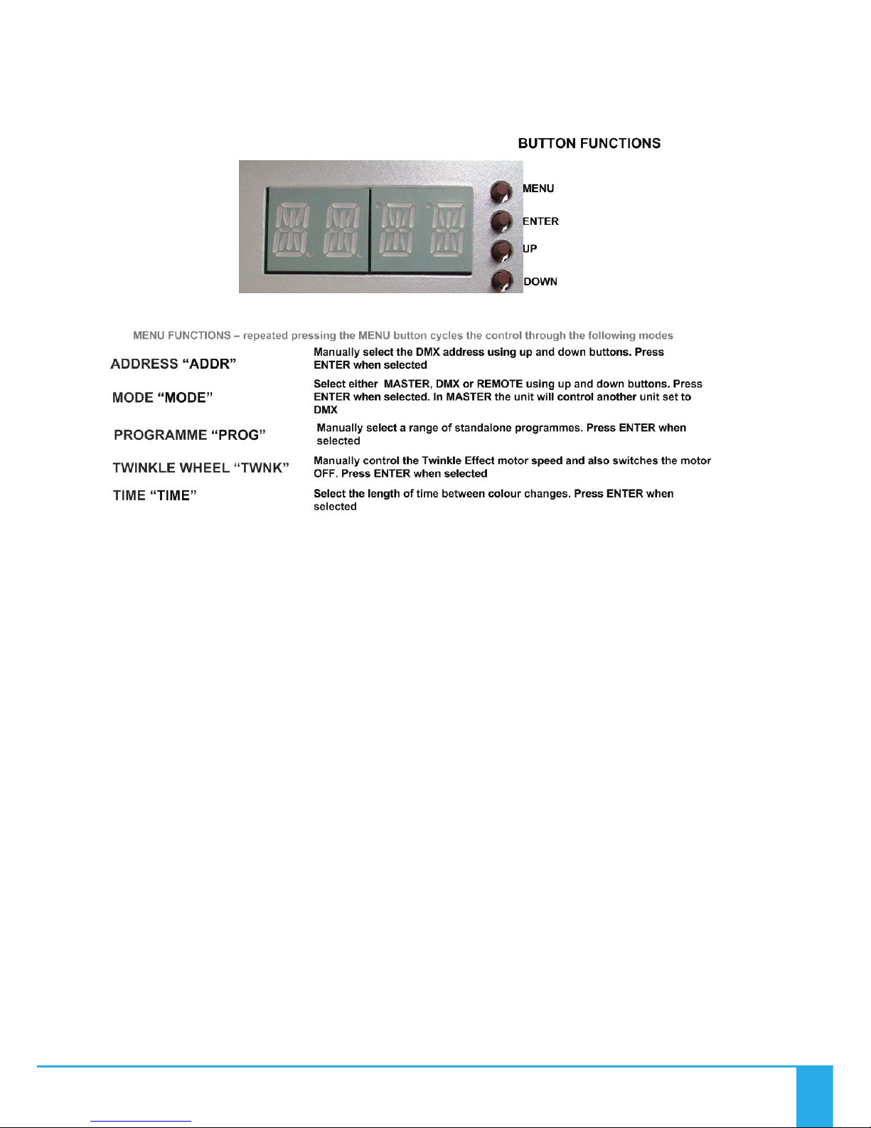
OPERATION
Rear Panel Controls
The le hand display shows a rotatin line when DMX data is received.
Standalone Remote Mode
A ain in this mode the illuminator (set to Remote) can be used in two ways –
either as a sin le independent illuminator or in a Master/Slave confi uration
with several illuminators connected to ether usin DMX cables. The Master
color sequences are controlled by a RF remote control and a ain the Slave
will mimic the Master Illuminator
Standalone Master Mode
In this mode the illuminator (set to Master) can be used in two ways – either
as a sin le independent unit or in a Master/Slave confi uration with several
illuminators connected to ether usin DMX cables. The Slave (set to DMX) will
mimic whatever standalone pro ramme the Master illuminator is set to. All
menu functions are available in Master mode.
Note: for master/slave to operate, both master & slave units must be set to
address 001 only.

Nova Illuminator Ran e
6
OPERATION
DMX Mode
In this mode the Illuminator (set to DMX) can be controlled either by another
NOVA in Master mode or by a DMX controller.
Nova Remote Controller
Description Details Co ents
Power 2 X AAA batteries
Range 30 metres Measured in free space, may be attenuated by
obstructions or other RF devices
Frequency 2.4GHz Approved for use in UK, Europe and USA
Batteries – With The LED Illuminator powered up as described above, remove the rear cover
on Remote Controller. Ta ing care not to touch any of the front cover buttons, insert the
batteries. If you touch the remote control buttons when insertin the batteries it WILL effect
the operation of your Remote Control. If you do accidentally touch any of the buttons,
remove the batteries and start a ain.Once the batteries are inserted do not use the Remote
Control for 3 seconds.
Test remote control as detailed on the followin pa e. The Remote Controller is “matched”
to the Illuminator at the factory. If the Remote Controller is not matched or and additional or
replacement Remote Controller is required carry out the “Matchin Remote to Illuminator”
instructions in the followin text. If a Remote Controller is to be removed from control of a
Illuminator carry out the “Unmatchin Remote to Illuminator” instructions in the followin
text.
DO NOT TOUCH THE
BUTTONS WHILST
INSERTING
BATTERIES

Universal Fiber Optics 7
OPERATION
Remote Operation
No Description Function
01 Button Power ON
02 Button Power OFF
03 Color Ring Touch control all colors (White not available)
04 Indicator Indicates Controller active when buttons pressed
05 Button Increase color cycle speed
06 Button Increase Brightness
07 Button Decrease Brightness
08 Button Decrease Color cycle speed
09 Button Mode + Step up through Color cycle programmes
10 Button Mode - Step down through Color cycle programmes
2. OFF
3. Color Ring
9. Mode +
10. Mode -
1. ON
4. Indicator Light
5. Speed +
6. Brightness +
7. Brightness -
8. Speed -
REMOTE CONTROLLER OPERATION
Matching Remote to Illuminator – Remove the power plu from the rear of the Illuminator,
then replace and once the Indicator Li ht (4.) li hts, touch button 5 within 3 seconds, the
Illuminator will “blink” twice slowly indicatin that the Remote Controller is matched to the
Illuminator.
Once the remote is matched, follow the procedure on pa e 10 to put the illuminator into
remote pro ramme mode. The illuminator should then respond to remote commands.
Unmatching Remote from Illuminator - Remove the power plu from the rear of the
Illuminator, then replace and once the Indicator Li ht (4.) li hts, touch and hold button 5
within 3 seconds and the Illuminator will “blink” 9 times indicatin that the Remote
Controller is unmatched from the Illuminator.

Nova Illuminator Ran e
8
OPERATION
Remote Controller Modes and Functions
No Mode Brightness Speed Co ent
1Static White Ad ustable Not Ad ustable To revert to 1 (Static White) at any
time touch Color Ring then Mode+
2White and Colors
mixed Ad ustable Not Ad ustable
Color Ring control – brightness
ad ust Color only, not White. To
revert to 2 (Color Ring) at any time
touch color ring
3All Colors fade
change Ad ustable Ad ustable No White
4RGBW fade
change Ad ustable Ad ustable Red, Green, Blue & White
5RGBW snap
change Ad ustable Ad ustable Red, Green, Blue & White
67 Colors snap
change Ad ustable Ad ustable White and Colors mixed
72 Colors snap
change Ad ustable Ad ustable Red & White
82 Colors snap
change Ad ustable Ad ustable Blue & White
92 Colors snap
change Ad ustable Ad ustable Green & White
10 1 Color Flash Ad ustable Ad ustable Red
11 1 Color Flash Ad ustable Ad ustable Blue
12 1 Color Flash Ad ustable Ad ustable Green
13 1 Color Flash Ad ustable Ad ustable White
14 All Colors snap &
fade Ad ustable Ad ustable Random
Mode Buttons – This is not a loop, i.e. touchin the Mode+ button will not eventually brin
you back to Mode 1. To revert to Mode 1, either touch Mode – button repeatedly to step back
up throu h the Mode numbers, or touch Color Ring then Mode+
Color Ring –The Color Rin can be used to select individual colors by touchin the rin and
slidin your fin er around the rin ,
Brightness – bri htness can be increased or reduced in any mode usin buttons 6 & 7
Cycle Speed – speed of color cyclin in Modes 3 to 14 can be adjusted usin buttons 5 & 8
Universal Fiber Optics 9
OPERATION
Remote Range Wal Test
Once the Illuminator is fully installed carry out a complete ran e walk test and record the ran e in the
table below. This information is essential for maintenance purposes to determine if the
ran e/sensitivity is reducin and also to record dead areas within the Remote Controller’s ran e due to
RF obstructions and/or RF interference.
NOTE: Where a Illuminator has more than one Remote Control, reduction in operatin ran e may be
experienced when both (or multiple) Remote Controls are used simultaneously.
Description Date Max Range
Controller 1
Controller 2
Controller 3
Dead Areas

PROGRAMMING
Nova Illuminator Ran e
10
Other manuals for NOVA DMX
2
This manual suits for next models
3
Table of contents
Other UFO Dj Equipment manuals


