APPLICATIONS
DUAL-TRACE
APPLICATIONS
Introduction:
Themostobviousandyetthemostusefulfeature
ofthedual-traceoscilloscopeis
that
ithasthe
capabilityforsimultaneouslyviewingtwo
waveforms
that
arefrequencyorphase-related,or
that
havea commonsynchronizingvoltage,
such
as
in
digital
circuitry.Simultaneouslyviewingofinput
andits
output
isaninvaluableaidtothecircuit
designerortherepairman.Severalpossible
applicationsofthedual-traceoscilloscope
will
be
reviewedindetailtofamiliarizetheuserfurtherin
thebasicoperationofthisoscilloscope.
Frequency
DividerWaveformsViewing:
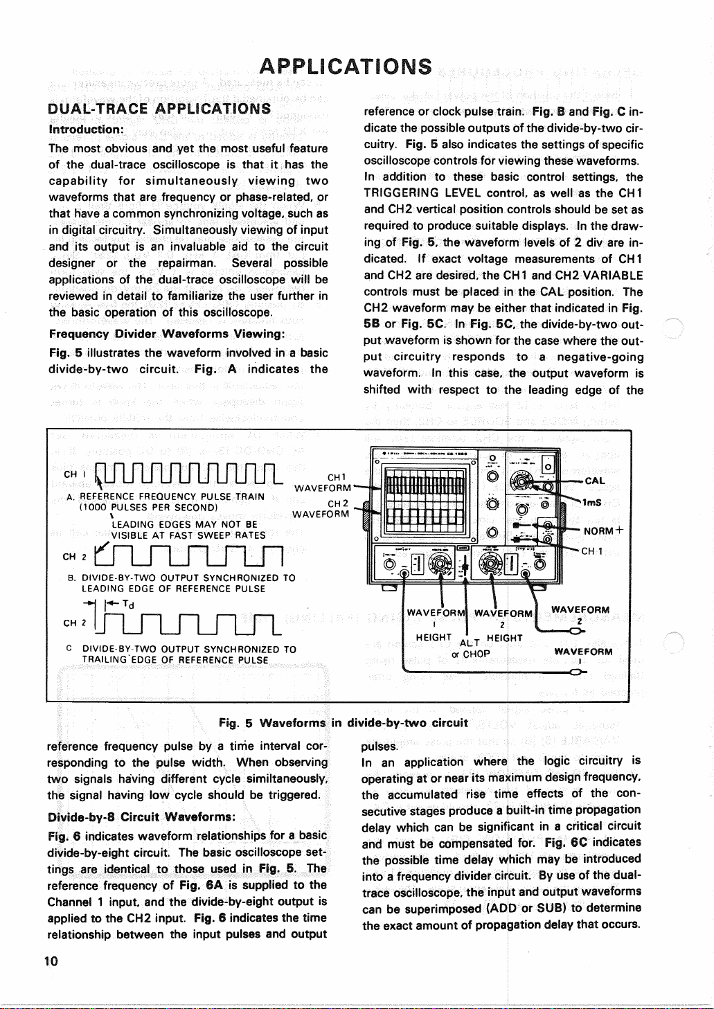
Fig.
5 illustratesthewaveforminvolvedina basic
divide-by-twocircuit.Fig.A indicatesthe
referenceorclockpulsetrain.Fig.B andFig.C in-
dicatethepossibleoutputsofthedivide-by-twocir-
cuitry.Fig.6 alsoindicatesthesettingsofspecific
oscilloscope
controlsforviewingthesewaveforms.
Inadditiontothesebasiccontrolsettings,the
TRIGGERING
LEVEL
control,aswellastheCH1
andCH2verticalpositioncontrolsshouldbesetas
requiredtoproducesuitabledisplays.Inthedraw-
ingofFig.5,thewaveformlevelsof2 divarein-
dicated.IfexactvoltagemeasurementsofCH1
andCH2aredesired,theCH1andCH2VARIABLE
controlsmustbeplacedintheCALposition.The
CH2
waveformmaybeeither
that
indicatedinFig.
5B
orFig.5C.InFig.5C,thedivide-by-twoout-
putwaveformisshownforthe
case
wheretheout-
putcircuitryrespondstoa negative-going
waveform.Inthis
case,
the
output
waveformis
shifted
with
respecttotheleadingedgeofthe
Fig.
5 Waveformsindivide-by-twocircuit
referencefrequencypulsebya
time
intervalcor-
respondingto thepulsewidth.Whenobserving
twosignalshaving
different
cyclesimiltaneously,
thesignalhavinglowcycleshouldbetriggered.
Divide-by-8CircuitWaveforms:
Fig.
6 indicateswaveformrelationshipsfora basic
divide-by-eightcircuit.Thebasicoscilloscopeset-
tingsareidenticaltothoseusedinFig.5.The
referencefrequencyofFig.6Aissuppliedto the
Channel
1 inputandthedivide-by-eight
output
is
appliedtotheCH2input.Fig.6 indicatesthe
time
relationshipbetweentheinputpulsesand
output
pulses.
Inanapplicationwherethelogiccircuitryis
operatingatornearitsmaximumdesignfrequency,
theaccumulatedrise
time
effectsofthecon-
secutive
stagesproducea
built-in
time
propagation
delaywhichcanbesignificantina criticalcircuit
andmustbecompensatedfor.Fig.6Cindicates
thepossible
time
delaywhichmaybeintroduced
into
a frequencydividercircuit.Byuseofthedual-
trace
oscilloscope,
theinputand
output
waveforms
can
besuperimposed(ADDorSUB)to determine
theexactamountofpropagationdelay
that
occurs.
10
A.
REFERENCE
FREQUENCY
PULSE
TRAIN
(1000
PULSES
PERSECOND)
LEADING
EDGES
MAYNOTBE
VISIBLE
AT
FAST
SWEEP
RATES
B.DIVIDE-BY-TWOOUTPUTSYNCHRONIZEDTO
LEADING
EDGE
OF
REFERENCE
PULSE
C
DIVIDE-BY-TWOOUTPUTSYNCHRONIZEDTO
TRAILING
EDGE
OF
REFERENCE
PULSE