TriCom TCR-MBA-75 User manual

OPERATOR'S MANUAL
TCR-MBA-75 NBT
MULTI-BAND RF AMPLIFIER
DAMA CERTIFIED
DOCUMENT # 90400-01076 REV D
Tricom Research, Inc. http://www.tricomresearch.com
17791 Sky Park Circle, Suite J, Irvine, CA 92614
Ph: (949) 250-6024 fax: (949) 250-6023

TCR-MBA-75 NBT OPERATOR’S MANUAL
i
TABLE OF CONTENTS
1.0 INTRODUCTION
1.1 General Information .......................................................................................1
1.2 Abbreviations and Glossary ...........................................................................2
1.3 Equipment Description ..................................................................................3
1.4 Features ..........................................................................................................3
1.5 TCR-MBA-75 NBT System ..........................................................................4
1.5.1 Amplifier Components...................................................................................4
1.5.2 Power Cable ...................................................................................................4
1.6 Specifications .................................................................................................4
2.0 OPERATION
2.1 General Information .......................................................................................6
2.2 Controls, Indicators, and Connectors .............................................................7
2.3 Operational Procedures ..................................................................................8
2.3.1 General Information .......................................................................................8
2.3.2 Equipment Set-up...........................................................................................8
2.3.3 Operating Procedures .....................................................................................8
2.3.3.1 Normal Operation ..........................................................................................8
2.3.3.2 MBITR Specific Operation ............................................................................9
2.3.3.3 Remote Operation…………………………………………………………...10
2.3.3.4 Out of Band Operation…………………………………………………... ....11
2.3.3.5 Bypass Operation ...........................................................................................11
2.3.3.6 Troubleshooting .............................................................................................11
2.3.3.7 Collocation……………………………………………. ................................11
3.0 INSTALLATION
3.1 General Information .......................................................................................12
3.2 Preparation for Use ........................................................................................12
3.3 Cable Interconnections ...................................................................................12

TCR-MBA-75 NBT OPERATOR’S MANUAL
ii
LIST OF TABLES
Table 1-1 TCR-MBA-75 General Operating Parameters .........................................4
Table 1-2 TCR-MBA-75 Interconnect Characteristics ............................................6
Table 2-1 TCR-MBA-75 Controls, Indicators, and Connectors ..............................8
Table 2-2 TCR-MBA-75 System Troubleshooting Guide………. ..........................12
Table 3-1 DC Input Power connector pin out…………………………………......13
LIST OF FIGURES
Figure 1-1 TCR-MBA-75 NBT System Components ...............................................1
Figure 2-1 TCR-MBA-75 NBT Controls and Indicators ..........................................7
Figure 2-2 TCR-MBA-75 NBT Connectors ..............................................................7
Figure 2-3 Mode, Power and LNA Flow Chart…………………………………… .9
Figure 2-4 Bias Tee I For Remote Operation………………………………………10
Figure 2-5 Remote Operation Setup…………………………………………….….11
Figure 3-1 TCR-MBA-75 NBT DC Input Connector pin location...……………… 13
Figure 3-2 Amplifier Mounting Dimensions……………………....……………… .14
Note: The information contained herein is for reference only and does not constitute a
warranty of performance.

TCR-MBA-75 NBT OPERATOR’S MANUAL
iii
Revision History - Document 90400-01076
Revision Description Date
Rev A Initial Release 22 JUNE 2010
Rev B Added Fi
g
ure 3-2 Amplifier Mountin
g
Dimensions 29 MAY 2013
Rev C Reconcile technical data and data sheets 02 APR 2018
Rev D Revise 2.3.3.3 Remote Operatio
n
31 OCT 2018
1 | Page
1.0 INTRODUCTION
1.1 GENERAL INFORMATION
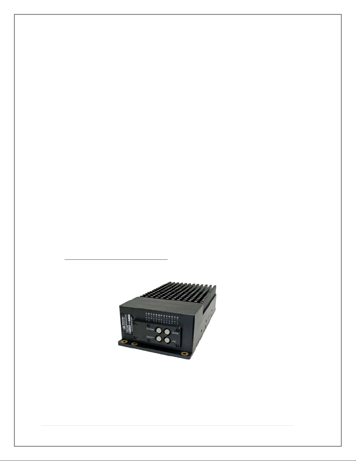
This manual provides operating instructions for the DAMA certified TCR-MBA-
75 NBT Multiband Amplifier shown in Figure 1-1. The designation NBT (non-
bias tee) simply indicates the ability to use the amplifier without the need for a
bias tee by using the front panel DC connector. The TCR-MBA-75 NBT is
designed as a form and fit replacement for the AM-SAT-50 UHF SATCOM or
TCR-MBA-75 Amplifier with enhanced functionality. The footprint and
mounting provisions for the AM-SAT-50, TCR-MBA-75 and TCR-MBT-75 NBT
are identical. The TCR-MBA-75 NBT is an amplifier/pre-amplifier designed to
provide transmit and receive gain for:
Multiband line of sight (LOS) 30~512 MHz communications;
HAVEQUICK 225-400 MHz and SINCGARS frequency hopping 30~88
MHz operation; and,
UHF Tactical SATCOM (242~268 MHz receive and 292~318 MHz
transmit) frequencies with Low Noise Amplifier (LNA) and Cosite
suppression.
Part number: 11000-00678
The TCR-MBA-75 NBT is DAMA Certified with several UHF SATCOM
terminals. For a listing of the current certifications please see the Joint
Interoperability Test Command (JITC) Website:
http://jitc.fhu.disa.mil/reg/dama.html
Figure 1-1. TCR-MBA-75 NBT Amplifier

2 | Page
1.2 ABBREVIATIONS AND GLOSSARY
AGC Automatic gain control
ALC Automatic level control
AM Amplitude modulation
ANT Antenna
BPS Bits per second
CT Cipher text
CW Continuous wave
COMSEC Communications security
dB Decibel
dBm Decibel referenced to 1 milliwatt (0 dBm = 1 mW)
FM Frequency modulation
Hz Hertz
IW Integrated Waveform
JITC Joint Interoperability Test Center (DISA)
KHz Kilohertz
LED Light emitting diode
LNA Low Noise Amplifier
LOS Line of sight
MHz Megahertz
mW Milliwatt
PT Plain text
PTT Push to Talk
RCV Receive
SATCOM Satellite Communications
UHF Ultra-high frequency
VDC Volts, direct current
VSWR Voltage standing wave ratio
W Watt
X-MODE Connector for COMSEC equipment
XMT Transmit

3 | Page
1.3 EQUIPMENT DESCRIPTION
The TCR-MBA-75 NBT Multi-band RF Amplifier operates in 30 MHz to 512
MHz AM and FM Line-of Sight (LOS), 30 MHz to 88 MHz SINCGARS Frequency
Hopping, 225 MHz to 400 MHz HAVEQUICK, and UHF Tactical SATCOM modes. It
is suitable for vehicular, airborne, or fixed-station applications and is compatible with
most military and commercial radios operating in the 30-512Mhz frequency spectrum.
The amplifier is weather-resistant and may be located outdoors with the antenna via Bias
Tee I (for information on this see Para. 2.3.3.1 Normal Operations). The operation of the
amplifier is controlled via front panel push button switches. The amplifier has a single
power connection, an RF input port and two frequency specific output antenna ports. The
LOS port is for frequency hopping and multiband Line of Site operation anywhere
between 30 and 512 MHz. The SATCOM port is used with UHF SATCOM antennas in
the 292-318 MHz uplink and 242-268 MHz downlink bands. The Mode push button
switch provides for selection of LOS AM or FM, SATCOM, Frequency Hopping
(SINCGARS), and Frequency Hopping AM (Have Quick). The LNA push button switch
allows the LNA to be enabled or disabled in SATCOM. The TX power push button
switch provides the amplifier output power selection in SATCOM mode. Some
equipment that is compatible with the TCR-MBA-75 NBT includes but is not limited to:
LOS, multiband and SATCOM radios, including the AN/PRC-148 JEM and
MBITR, the AN/PSC-5 series, AN/PRC-117F, AN/PRC-117G AN/PRC-152
Falcon III Handheld, and the AN/PRC-119 SINCGARS terminals.
Directional and broadband antennas with 50 Ohm impedance
Conditioned power from a 28 VDC nominal source.
1.4 FEATURES
The TCR-MBA-75 NBT has the following features:
JITC DAMA Certified
Coverage from 30 to 512 MHz, including SINCGARS FM and HAVEQUICK
AM Frequency Hopping compatibility
IW Compatibility
Connections for both a SATCOM and an LOS antenna
Pre-amplification of received RF signals from antennas in SATCOM mode
Power amplification of transmit signals to 35, 50 or 75 Watts in SATCOM
mode

4 | Page
Transmit and receive band filtering to suppress interference from
co-located radios and amplifiers in SATCOM mode
Amplifier front panel indication of system status
1.5 TCR-MBA-75 NBT SYSTEM
The TCR-MBA-75 NBT is pictured in Figure 1-1.
1.5.1 Amplifier Components
The Amplifier consists of several printed circuit assemblies, a filtering and
switching network, and RF connectors housed in an environmentally sealed aluminum
housing. With normal care and maintenance, the assembly is highly resistant to corrosion
from the elements. The RF connections to the RF input, SATCOM and LOS antennas
are Female Type N. Power to operate the amplifier is applied via a cable connected to
the 5 pin circular Mil DC input connector. A 3ft Power cable is supplied with each
system.
1.5.2 Power Cable
A multi-conductor cable connects the amplifier with a 28 VDC power source. A
wiring diagram for the cable is shown in Section 3 of this manual. The cable is identical
to the power cable used for the AM-SAT-50 and AM-SAT-100 amplifiers.
1.5.2.3 Optional components
An optional Bias Tee I may be used to remotely power the TCR-MBA-75 NBT
and allow it to be placed closer to the antenna to over come system transmit and receive
losses and improve receive signal strength utilizing the built in Satcom Low Noise
Amplifier (LNA) in the TCR-MBA-75 NBT.
1.6 Specifications
The operating parameters, physical characteristics, and environmental specifications are
shown in the following tables.
Table 1-1. TCR-MBA-75 Nominal Performance Specifications
TRANSMIT SECTION
SATCOM OPERATION
Frequency Range 292-318 MHz
Input Power 5 Watts typical (2-20 Watts)
Output Power 35/50/75 Watts
Switching Speed DAMA Certified/IW compatible
Modulation FM or multiphase, 5 or 25 KHz bandwidth

5 | Page
Filtering Cosite suppression
Harmonics -60 dBc
LOS OPERATION
Frequency Range 30-512 MHz
Band Selection Fully automatic
Input Power 5 Watts typical (2-20 Watts)
Output Power 50 Watts FM, 25 Watts CW AM
Modulation AM, FM or multiphase, 5 or 25 KHz bandwidth
Harmonics -60 dBc
FREQ HOP OPERATION
Frequency Range 30-88 MHz FM (SINCGARS)
225-400 AM (HAVEQUICK)
Band Selection Fully automatic
Input Power 5 Watts typical (2-20 Watts)
Output Power 50 Watts FM, 25 Watts CW AM
Harmonics -60 dBc
RECEIVE SECTION
SATCOM OPERATION
Frequency Range 242-268 MHz
Noise Figure 3.5 dB
Receive Gain 10 dB (or bypass LNA)
Filtering Cosite Suppression
LOS OPERATION
Frequency Range 30-512 MHz
Insertion Loss 1.5 dB
ADDITIONAL SPECIFICATIONS
Input/Output VSWR 2.0:1
RF Connections Type N female
Protection VSWR, temperature
Indicators DC PWR, LOS, SATCOM, F HOP, TX,
LNA, TX PWR Level, TEMP, Fault
DC Power 24-32 VDC
Operating Temperature -30 to +60 C
Bypass Operation Routes Radio signal to LOS port
Dimensions 3” H x 6” W x 12” L
Weight 12 lbs.
Controls Mode: SATCOM, LOS, FREQ HOP, AM
Transmit Power Level
LNA on/off

6 | Page
DC on/off
Environmental IP-67
Table 1-2. TCR-MBA-75 Interconnect Characteristics
Connection Signal/Pin
Connector Function
AMPLIFIE
R
DC IN DC power input
PIN A
PIN B
PIN C
PIN D
PIN E
MS3102E-14S-5P
(mating connector for cable use
is MS3106F-14S-5S)
+28 VDC Input
+28 VDC Input
Electrical GND
Electrical GND
+28 VDC Input
RADIO RF fro
m
radio T
y
pe N female
LOS
SAT
To LOS Antenna
To SATCOM Antenn
a
Type N female
T
y
pe N female
2.0 OPERATION
2.1 General
This section provides information for operating the TCR-MBA-75.
WARNING
Electromagnetic radiation from the antenna can damage eyes and other body tissue
when the system is transmitting. DO NOT stand directly in front of the antenna or
in close proximity to the sides or back of the antenna when transmitting.
Other manuals for TCR-MBA-75
1
Table of contents
Other TriCom Amplifier manuals


