TRENCHERPRO 26-183 User manual

TRENCHER PRO
Mini-Trencher
Operator’s Manual
26-183: 16” Trencher
26-184: 20” Trencher
26-185: 27” Trencher
Product registration form attached to the back of this booklet. Mail your registration within 2
weeks of date of purchase.

Parts and Design
Power Head *
* 16” & 20” con gurations sold with
Husqvarna K770 power head; 27” sold
with Husqvarna K970.
Welcome!
Thanks for buying a TrencherPro! We design our products to meet the high demands
of our industrial and commercial clients, with ease-of-use that’s aimed at homeowners
and do-it-yourselfers. That means that our products are tough enough to meet rigorous
industry standards, but designed for non-professionals to learn to use. We warranty all
TrencherPro parts for one year from purchase date. Register your product today.
If you have feedback or questions, we want to know!
Mini-Trencher
TRENCHER PRO
This user guide/manual covers assembly, use, basic service and troubleshooting information for Tren-
cherPro parts (“digging-head drive adaptor”), including:
• mounting and installing the digging chain and chain guard;
• assembling the trenching cart;
• instructions for basic operation.
For more information about use and maintenance of the power head refer to operator’s manual pro-
vided.

WARNING!
WEAR PERSONAL
PROTECTIVE EQUIPMENT
Failure to follow warnings, cautions, or assembly
and operation instructions in this manual may
result in serious injury or death.
Read this operator’s manual before operation!
●Do not permit children to operate this
equipment at any time. Do not permit others
that have not read and understood this
manual to operate the mini-trencher.
●Keep all people and pets a minimum of
10 feet away from the work area when
operating the mini-trencher. Only the
operator should be near the mini-trencher
during use.
●Do not operate this device when under the
inuence of alcohol, drugs or medication.
●Do not allow a person who is tired, not
completely alert, or otherwise impaired to
operate the mini-trencher.
●Always check with authorities for
underground utilities before digging
trenches. Serious injury or death could
result from contact with gas or electric lines.
●Read the power head operation manual
concerning the use and maintenance of
power head.
●Make sure that all safety guards are in
place and securely fastened. Do not operate
if any guards are missing.
●Make sure that the digging chain is
correctly installed, oriented, and in good
working condition prior to use.
We recommend operating this minitrencher with
the cart.
Death or serious injury can result from
entanglement with moving parts.
GENERAL SAFETY
KEY TO SYMBOLS
Notice:
Tip
Indicates the possibility of death
or serious injury.
Indicates the possibility of injury
to self or damage to equipment.
Indicates additional information.
3
Important Safety Information
Read and thoroughly understand all instructions
and safety information before assembling or
operating this mini-trencher. Failure to do so
may result in serious injury or death. Do not
allow anyone who has not read this manual to
operate the device. As with all power equipment, a
trencher can be dangerous if assembled or used
improperly. Do not operate if you have doubts or
questions concerning safe operation.
Call our customer service department at 720-
437-7640, or email us at customerservice@
tooltuffdirect.com if you have questions or
concerns about the safe operation of this
equipment.
When operating this minitrencher it is essential
that you wear safety gear including safety
glasses, steel toe shoes, well-tted gloves
(no loose cuffs or draw strings), and hearing
protection. We also recommend a face guard,
especially for hand-held applications.
Do not wear loose clothing or jewelry that can be
caught by moving parts. Keep clothing and hair
away from all moving parts while operating.

Safety Decals
Make sure all safety warning decals are attached and in readable condition. Replace
missing or defaced decals. Call 720-437-7640 for replacement decals.
1) Part # 29-036
2) Part # 29-037
1
1
1
2
4
Important Safety Information

INTENDED USE REASONABLY FORESEEABLE
MISUSE
5
General Use Guidelines
This device is designed and tested for use
digging narrow (2-3”) trenches from 16-27” in
depth (depending on conguration) in most soil
types. It is not intended to cut solid surfaces
such as tarmac or concrete. Excessively rocky
soil types, soil with large heavy rocks, or soil with
roots measuring more than 2” in diameter can
damage the chain, drive adapter, or powerhead.
It is recommended for laying sprinkler lines,
drainage pipes, cables, root barriers, and related
applications. Do not use the mini-trencher for
any purpose other than digging trenches in the
suitable soil. Any other use is unauthorized and
may result in serious injury or death.
We recommend that you use the cart when
digging trenches. It reduces fatigue and keeps
you at a safe working distance from moving
parts and debris. However, it is possible to use
the trencher without the cart if the situation
demands.
Use common sense and stay safe!
The following constitutes improper use
and voids any warranty:
Notice:
Always check with authorities for
underground utilities before digging
trenches!
Serious injury or death could result from
contact with gas or electric lines.
• Attempting to cut wood or trim hedges
• Attempting to cut concrete, asphalt or tarmac,
or any solid surface
• Attempting to cut solid stone or rock
• Use in extremely rocky soil
In the course of digging a trench, the mini-
trencher may come into contact with unforeseen
objects such as large tree roots, large heavy
rocks, unmarked obstacles, etc. We consider this
reasonably foreseeable misuse and will work with
you to keep your mini-trencher operational.
Please contact our service department at:
customerservice@tooltuffdirect.com
or
720-437-7640
TRENCHER PRO

10
3
1
2
4
5
6
7
8
9
11
12
13
15
14 16
ref. # description part #
1 Main mount 26-114
2 Heavy-duty digging bar 26-115 / 26-179 / 26-180
3 (Chain bar) mounting plate 26-118
4 Chain guard 26-146
5 Drive sprocket 26-140
6 Plastic guard 26-147
7Rubber guard ap (x 2) 26-137
8M12 bolt (x 2); (1.25mm X 35mm)
9M12 lock washer (x 2)
10 M12 washer (x 2)
11 M8 bolt (x 2); (1.25mm X 14mm)
12 M8 lock washer (x 2)
13 M8 nylock nut (x 6)
Inset
14 Nose sprocket A (11 teeth) 26-170
15 Nose sprocket B (6 teeth) 26-120
16 M8 screw (x 3); (1.25mm X 20mm)
6
Mini-Trencher Parts Guide:
Digging-head drive adapter
Tip
Notice:
7
Step 1: Installing the Digging Bar
and Chain
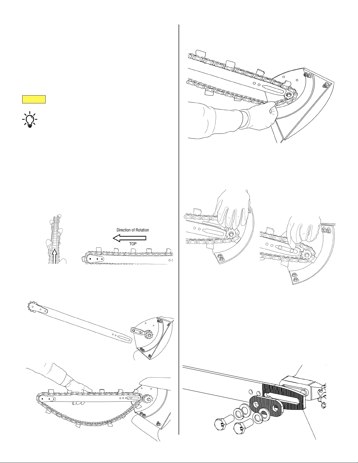
The heavy-duty digging bar [2] and chain are
disassembled for shipping. Before operating the
mini-trencher, you must install the digging bar
and chain, then tension the chain for the type of
material you will be working with.
1. Orient the digging chain correctly.
During operation, the chain rotates away from the
powerhead on the top side and returns on the bot-
tom, pulling loose material with it. e chain must be
oriented correctly, with the teeth opening towards the
loose material.
2. Mount the chain and chain bar.
A. Get the bar in position. Drape the digging
chain over the bar.
B. Seat the chain on both the nose sprocket
[14/15] and drive sprocket [5] as you mount
the bar.
C. Slide the slot into place. It should t snugly.
Use the M12 bolts [8], washers [10] and lock washers
[9] to attach the mounting plate [3], and tighten loose-
ly.
• Don’t tighten rmly until you tension the
chain.
Before you begin, locate the mounting plate [3],
M12 bolts [8], washers [10] and lock washers [9].
Read and understand the chain-tensioning
guide before operation.
3. Attach the mounting plate.

Notice:
Tip
Tip
8
Step 1, Continued:
4. Tension the chain.
Insert a athead screwdriver into the tensioning hole
in the chain bar. Force the bar out, away from the pow-
er head, until you reach the desired chain tension.
You may need to tap the bar back and start again if the
chain becomes too tight.
5. Attach the chain guard.
Use a socket wrench (not included) or impact driver to
rmly tighten the bolts.
Once the desired chain tension is reached, securely fas-
ten the mounting plate [3]. (See the Chain Tensioning
Guide for more details.)
Use a socket wrench (not included) or impact driver to
rmly tighten the bolts.
Review the chain-tensioning guide (next page)
carefully before operation.
Use the M8 bolts [11] and lock washers [12] to attach
the chain guard [4] onto the main mount [1].
e bolt holes are located above the drive sprocket [5].

Notice:
Soil type Chain tension
loose top soil;
hard, compacted soil;
clay
1”
between bottom of digging bar and inside
of digging chain
moderately rocky soil;
sandy, coarse soil
1 ½”
between bottom of digging bar and inside
of digging chain
Notice:
Notice:
Tip
Tip
9
Chain Tensioning Guide
Above: Chain is tensioned to 1” for normal top
soil.
Use the small end of the combination wrench
tool to measure approximate spacing between
bottom of digging bar and inside of digging
chain.
1”
Check chain tension occasionally during
operation!
• Chain tension can slip and may require
adjustment!
The chain tension must be adjusted according to
soil type.
1 ½”
Above: Chain is tensioned to 1 ½” for coarse
soil.
Use the large end of the combination wrench
tool to measure approximate spacing.
Tighten the bolts [8] rmly before use.
• We recommend using a socket wrench (not in-
cluded) or impact driver to make sure bolts are
tight.
too tight!
too loose!
Too much slack in the chain causes excessive
wear to external parts and may damage the
main mount and guards.
Over-tightening the chain may cause binding
and excess wear to the drive belt and/or clutch.

1
2
10
3
4
5
6
7
8
11
12
13
14
15
16
17
9b
9a
10
Step 2: Assembling the Cart
Lay out all the parts in an area where you have
plenty of space to assemble the cart. Locate the
axle [10C].
Cart Parts
ref. # description part #
1C grip 26-173
2C (throttle) lever 26-172
3C cable-tension adjuster
4C throttle cable 26-148
5C trigger-extension accessory
6C throttle-extension arm 26-129
7C pivot arm (spring-loaded
end faces axle) 26-133
8C shaft-locking pin
9C-a strap 26-131
9C-b strap plates (x 2)
10C axle
26-135
11C mounting lock
12C mounting guide
13C handle-mount bar
14C pivot plate
15C clevis pin
16C lynch pins (x 2)
17C wheels (x 2) 26-174
}
}
}
}
This manual suits for next models
2
Table of contents