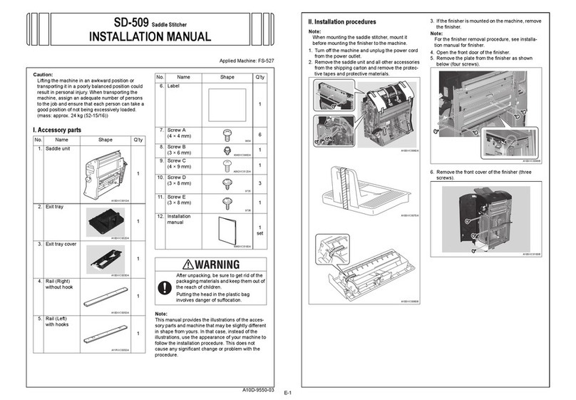
Toshiba MR-2012 User manual

AUTOMATIC DOCUMENT FEEDER
MR-2012
File No.31100013

General Precautions for Installation/Servicing/Maintenance for the MR-2012
The installation and service should be done by a qualified service technician.
1. When installing the MR-2012 to the Plain Paper Copier, be sure to follow the instructions described in
the “Unpacking/Set-Up Procedure for the MR-2012” booklet which comes with each unit of the
MR-2012.
2. The MR-2012 should be installed by an authorized/qualified person.
3. Before starting installation, servicing or maintenance work, be sure to turn off and unplug the copier
first.
4. When servcing or maintaining the MR-2012, be careful about the rotating or operation sections such
as gear, pulleys, sprockets, cams, belts, etc.
5. When parts are disassembled, reassembly is basically the reverse of disassembly unless otherwise
noted in this manual or other related materials. Be careful not to reassemble small parts such as
screws, washers, pins, E-rings, toothed washers to the wrong places.
6. Basically, the machine should not be operated with any parts removed or disassembled.
7. Delicate parts for preventing safety hazard problems (such as breakers, thermofuses, fuses, door
switches, sensors, etc.if any) should be handled/installed/adjusted correctly.
8. Use suitable measuring instruments and tools.
9. During servicing or maintenance work, be sure to check the serial No.plate and other cautionary
labels (if any) to see if they are clean and firmly fixed.If not, take appropriate actions.
10. The PC board must be stored in an anti-electrostatic bag and handled carefully using a wristband,
because the ICs on it may be damaged due to static electricity.Before using the wrist band, pull out
the power cord plug of the copier and make sure that there is no uninsulated charged objects in the
vicinity.
11. For the recovery and disposal of used MR-2012, consumable parts and packing materials, it is
recommended that the relevant local regulations/rules should be followed.
12. After completing installation, servicing and maintenance of the MR-2012, return the MR-2012 to its
original state, and check operation.
Copyright 2000
TOSHIBA TEC CORPORATION

October 2000 © TOSHIBA TEC 1 MR-2012 CONTENTS
CONTENTS
1. SPECIFICATIONS ...................................................................................................... 1-1
2. OUTLINE .................................................................................................................... 2-1
2.1 Names ofVarious Components......................................................................................... 2-1
2.2 Layout of Electrical Parts.................................................................................................. 2-2
2.3 Harness Connection Diagram............................................................................................ 2-4
2.4 Board Assembly ............................................................................................................... 2-5
3. OPERATIONAL DESCRIPTION ................................................................................. 3-1
3.1 GeneralOperation ............................................................................................................. 3-1
3.2 Block Diagram .................................................................................................................. 3-1
3.3 Detection of Abnormal Status ........................................................................................... 3-2
3.3.1 Cover open/Close detection ................................................................................... 3-2
3.3.2 Feeder jam detection ............................................................................................. 3-2
3.3.3 ADF registration sensor stay jam detection............................................................ 3-2
3.3.4 ADF read sensor unreached jam detection ............................................................ 3-2
3.3.5 ADF read sensor stay jam detection ...................................................................... 3-2
3.3.6 ADF exit sensor unreached jam detection.............................................................. 3-2
3.4 FlowChart ........................................................................................................................ 3-3
4. MECHANICAL DESCRIPTION.................................................................................. 4-1
4.1 Paper Feed System .......................................................................................................... 4-1
4.2 Document Size Detection Method..................................................................................... 4-2
4.3 Drive System .................................................................................................................... 4-4
5. CIRCUIT DESCRIPTION ........................................................................................... 5-1
5.1 PWA Block Diagram ......................................................................................................... 5-1
5.2 Detection Circuit ............................................................................................................... 5-1
5.3 ADF Read Sensor Input Circuit ......................................................................................... 5-2
5.4 ADF Motor Drive Circuit .................................................................................................... 5-3
5.5 Meaning of Signals ........................................................................................................... 5-4
5.6 Timing Chart ..................................................................................................................... 5-5
6. DISASSEMBLY AND REPLACEMENT..................................................................... 6-1

October 2000 © TOSHIBA TEC 1 - 1 MR-2012 SPECIFICATIONS
1. SPECIFICATIONS
Function : Auto document feeder
No.of originals loaded : Max.50 originals (A4, 60 to 80g/m2)
Document size : A5-R (Min.) to A3 (Max.)
Dimensions : 530 (W) x 450 (D) x 120 (H) mm
Weight : Approx. 5.4 kg
Power supply : 5V, 24V (Supplied from copier)

October 2000 © TOSHIBA TEC 2 - 1 MR-2012 OUTLINE
2. OUTLINE
2.1 Names of Various Components
Connection Cable
ADF 02-01-01
ADF top cover
Document guide R
Document tray
Document guide F

MR-2012 OUTLINE 2 - 2 October 2000 © TOSHIBA TEC
2.2 Layout of Electrical Parts
VR1
SW1
SEN1
SEN5
SEN4
SEN6
SEN3
SEN2
ADF 02-02-01
M1
ADF PWA
ADF 02-02-02

October 2000 © TOSHIBA TEC 2 - 3 MR-2012 OUTLINE
Symbols and functions of various devices
Name
ADFCOV-SW
ADF top cover open switch
WIDTH-VR
Document width sensor
ADFOPN-SEN
ADF open sensor
SIZE-SEN
Document length sensor
EMPTY-SEN
Document empty sensor
REGST-SEN
ADF registration sensor
POS-SEN
ADF read sensor
HAISI-SEN
ADF exit sensor
ADF PWA
ADF-MOT
ADF motor
Function
Detects the open/close state of the top cover
during jamming processing, etc.
Detects the width of document.
Detects the open/close state of the ADF unit.
Detects the length of document.
Detects the loading of document.
Detects the aligning position of document.
Detects the document scanning start position.
Detects the ejection of document.
PWA which relays the sensor signals and motor
drive signals.
Drives the roller to transport originals.
Symbol
SW1
VR1
SEN1
SEN2
SEN3
SEN4
SEN5
SEN6
ADF
M1

MR-2012 OUTLINE 2 - 4 October 2000 © TOSHIBA TEC
2.3 Harness Connection Diagram
Scanner control PWA
CN6
SIZE2/DF-REQ
HAISI/DF-ACK 21
22
RADF CNT
ADF CNT/REQ 23
24
NC FG FG
SG 25
26
+24V
+24V 1
2
/A
A3
4
/B
B5
6
PG
PG 7
8
D/A
+5V 9
10
REGST/ACK
POS 11
12
5VPS
VALID/DFFAN 13
14
DF OPN
EMPTY 15
16
SG
COVER/RXD 17
18
SG
WIDTH/TXD 19
20
ADF PWA
21
22
1
2
3
4
5
6
7
8
9
10
11
12
13
14
15
16
17
18
19
20
21
22
23
24
25
26
1
2
3
4
5
6
7
8
9
10
11
12
13
14
15
16
17
18
19
20
NC NC
NC
NC
NC
CN1
SG
HAI+5V
HAISI
1
2
3
ADF
top cover open switch
ADF exit sensor
3
2
1
N.C.
N.O.
COM
CN11
CN10
CN9
CN6
CN12
POS
+5V
D/A
4
5
6
ADF read sensor
3
2
1
SG
REG+5V
REGST
7
8
9
ADF registration
sensor
3
2
1
SG
EMP+5V
EMPTY
10
11
12
Document empty sensor
3
2
1
SG
OPN+5V
DF_OPN
13
14
15
ADF open sensor
3
2
1
CN12
Document length sensor
3
2
1
+24V
MOT+24V
COVER
CN2
CN4
1
2
3
WIDTH
WIDTH+5V
SIZE+5V
SG
SG
CN5
1
2
3
4
5
SIZE 6
Document
width
sensor
MOT+24V
MOT+24V NC
NC
NC
NC
NC
/A
A
B
CN3
1
2
3
4
5
1
2
3
4
5
/B 6
6
7
8
9
10
11
ADF motor
ADF
ADF 02-03-01

October 2000 © TOSHIBA TEC 2 - 5 MR-2012 OUTLINE
2.4 Board Assembly
ADF 02-04-01

October 2000 © TOSHIBA TEC 3 - 1 MR-2012 OPERATIONAL DESCRIPTION
3. OPERATIONAL DESCRIPTION
3.1 General Operation
The ADF is an auto document feed unit capable of accommodating a maximum of 50 originals. The
originals loaded are fed and scanned one by one and stacked on the exit tray. The ADF has a mechanical
section for document transport, sensors to detect the position of document, etc., and a motor for transport.
It also has one PWA where comparator IC’s only are installed and the other signals simply pass. For this
reason, all control and processing are performed by the scanner PWA.
3.2 Block Diagram
ADF 03-02-01
ADF
PWA
ADF
CN6
CN1
Scanner
PWA
ADF read sensor
ADF open cover sensor
Document length sensor
Document width sensor
ADF top cover open switch
CN4CN5
ADF registration sensor
Document empty sensor
ADF exit sensor
ADF motorM
CN2CN3
Table of contents
Other Toshiba Printer Accessories manuals

Toshiba
Toshiba MY-1016 User manual

Toshiba
Toshiba MR-2017 User manual

Toshiba
Toshiba SmartLink e-STUDIO16 User manual

Toshiba
Toshiba digital copiers User manual

Toshiba
Toshiba MY-1026 User manual

Toshiba
Toshiba GA-1190 User manual

Toshiba
Toshiba E-STUDIO AS/400 User manual
Toshiba
Toshiba SmartLink e-STUDIO16 User manual

Toshiba
Toshiba MD-0101 User manual

Toshiba
Toshiba MR-3022 User manual