Toro 30818 User manual

FormNo.3390-683RevB
HighLiftCollection,ParkingStandKit,andCarrier
Frame
Groundsmaster®3604-WheelDriveMulti-PurposeMachine
ModelNo.30818
ModelNo.30866—SerialNo.315000001andUp
ModelNo.30869—SerialNo.315000001andUp
InstallationInstructions
Important:FormachineswithaKubotaengine,kit30801mustbeinstalledonthemachine.Formachineswitha
Yanmarengine,kit30898mustbeinstalledonthemachine.
WARNING
CALIFORNIA
Proposition65Warning
ThisproductcontainsachemicalorchemicalsknowntotheStateofCaliforniato
causecancer,birthdefects,orreproductiveharm.
ThisproductcomplieswithallrelevantEuropeandirectives.Fordetails,pleaseseetheDeclarationofIncorporation(DOI)at
thebackofthispublication.
Safety
SafetyandInstructionalDecals
Safetydecalsandinstructionsareeasilyvisibletotheoperatorandarelocatednearanyareaofpotentialdanger.
Replaceanydecalthatisdamagedorlost.
132-4868
1.Crushinghazard—securethecylinderlocks.
132-4867
1.Crushinghazard—keepawayfromactuatingparts.
©2016—TheToro®Company
8111LyndaleAvenueSouth
Bloomington,MN55420
Registeratwww.T oro.com.OriginalInstructions(EN)
PrintedintheUSA
AllRightsReserved*3390-683*B
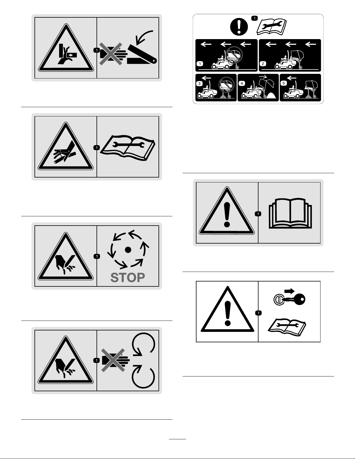
132-4866
1.Crushinghazard—keepawayfromactuatingparts.
132-4865
1.Puncturehazardofhand;uidunderpressure—read
theOperator’sManualbeforeservicingorperforming
maintenance.
132-4864
1.Cuttinghazard—waituntilallcomponentshavestopped
movingbeforeservicingthemachine.
132-4863
1.Cuttinghazard—keepawayfrommovingparts.
132-4862
1.Attention—readtheOperator’sManualbeforeperforming
maintenance;donottransportthevehiclewithafullhopper.
2.Onlytransportthevehiclewhenthehopperisalmostempty.
3.Donotremovethecollectionsystemwhenthehopperisfull.
4.Emptythecontentsofthehopperbeforestoringthe
collectionsystem.
5.Disengagethevehicleonlywhenthehopperisempty.
132-4861
1.Warning—readtheOperator’sManual.
132-4860
1.Warning—removethekeyfromtheignitionandreadthe
Operator’sManualbeforeperformingmaintenance.
2
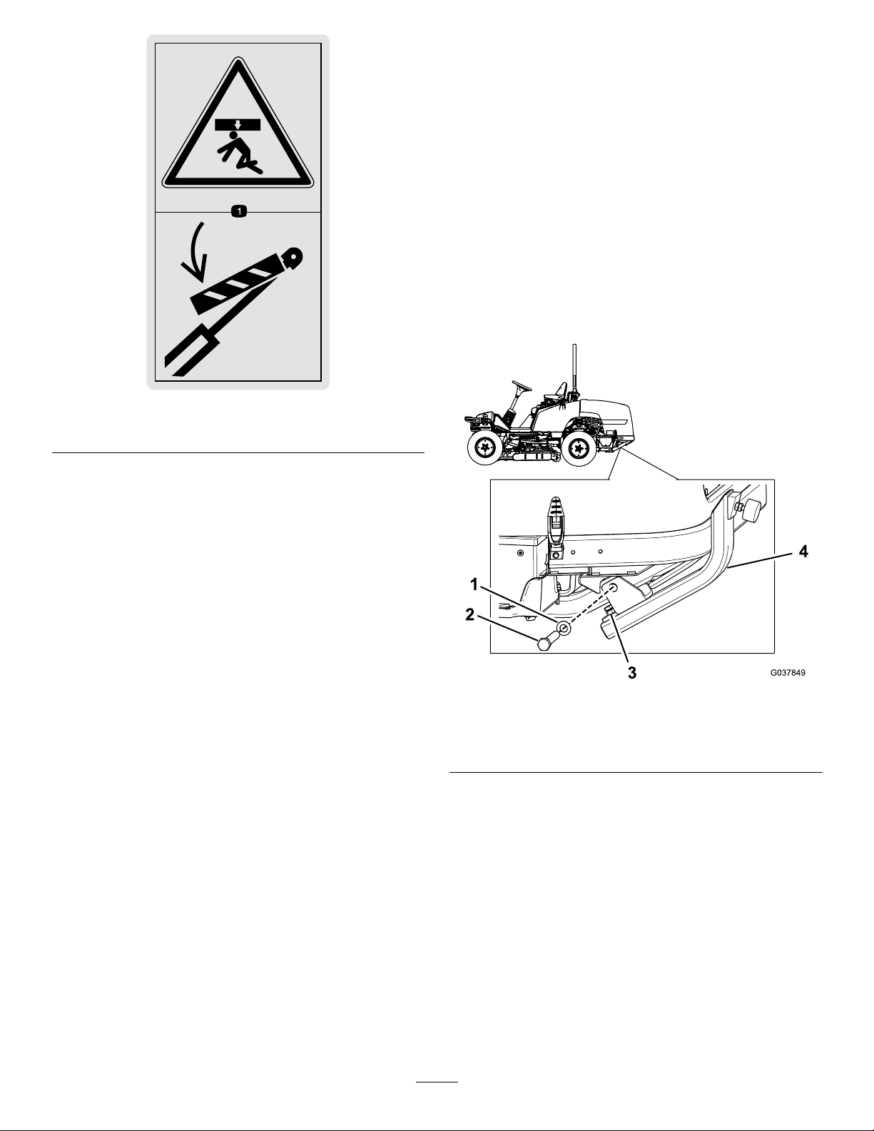
132-4859
1.Crushinghazard—securethecylinderlocks.
Installation
InstallingtheCarrierFrameKit
InstallingtheBumpers
1.Movethemachinetoalevelsurface,engagetheparking
brake,shutofftheengine,andremovethekeyfrom
theignition.
2.Loosenthejamnutontheadjustingboltontheendof
abumperandlowertheadjustingboltasfarasitcan
go(Figure1).
3.Installthebumpertothemachineframeusingalarge
bolt,washer,andnutfromthebumperassembly;do
nottightenthefasteners(Figure1).
Figure1
1.Largebolt(nutnotshown)3.Adjustmentboltandjam
nut
2.Washer4.Bumper
4.Adjustthebumpersothatitisparallelwiththeframe,
raisetheadjustmentboltuntilitcontactstheframe,
andsecureitwiththejamnut(Figure2).
3
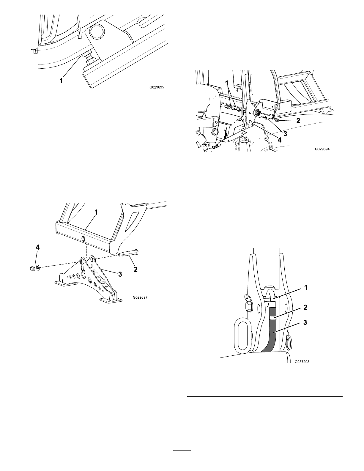
Figure2
1.Adjustmentboltagainsttheframe
5.Tightentheboltandnutsecuringthebumpertothe
frame.
6.Repeatthisprocedurefortheotherbumperonthe
othersideofthemachine.
AssemblingtheCarrierFrame
1.Blockthecastor-wheelassemblyinanuprightposition
usingjackstandsunderthecarrier-framecrossbar
(Figure3).
Figure3
1.Carrier-framecrossbar3.Castor-wheelassembly
(wheelsnotshown)
2.Pivotpin4.Locknutandwasher
2.Lowerthecarrier-framecrossbarintothetopofthe
wheelassemblyandsecureitwithapivotpin,washer,
andlocknut(Figure3).
3.PumpNo.2lithiumgreaseintothettingsoneach
endofthepinuntilgreasestartstocomeoutofthe
bearings.
InstallingtheCarrierFrame
1.Raisetherollbaronthemachineandinstallapinto
secureitononly1sideoftherollbar.
2.Ontheothersideoftherollbar,installaboltandnut
suppliedinthekitintotheholesinsteadofthepin
(Figure4).
Figure4
1.Pivotboltandtabbed
washer
3.Tabbedpin
2.Nut4.Boltreplacingthe
removablerollbarpin
3.Ontheleftsideofthemachine,loosentheclampon
thevent-linehoseandslidethehosedownthemetal
tube(Figure8).Tightentheclamp.
Note:Thisallowsyoutoinstallthecarrierframe
withoutitcontactingthehose.
Figure5
1.Metaltube3.Hose
2.Clamp
4.Removethepivotbolt,tabbedwasher,andnutfrom
therollbar;installthetabbedwasherandpivotbolt
fromtheinsideofthebar,butdonotinstallthenut
yet(Figure4).
4

5.Movethecarrierframeuptotherollbarbracketand
secureitusingatabbedpinthroughtherearholein
thebracket(Figure4).
Note:Placethetabovertheendofthepivotbolt.
6.Securethepivotboltandtabbedpinusingthenutyou
removedpreviously(Figure4).
7.Removethepinfromtheothersideoftherollbarand
repeatthisproceduretosecuretheothersideofthe
carrierframetothemachine.
Figure6illustratesthecorrectlyinstalledcarrierframe.
g029470
Figure6
Installingthe
High-Lift-CollectionKit
InstallingtheHigh-Lift-Collection
Assembly
1.Secureandliftthehigh-lift-collectionassemblyusing
ahoist.Ensurethatthestrapsyouusetohoistitonly
contactthesteelframeunderthehopper.
Important:Donotliftthegrasscollectorbythe
plastichopperoryouwilldamageit.
2.Slowlylowerthehigh-lift-collectionassemblyontothe
frameandslideitforwarduntilthecoolerassemblyon
thefrontofthehopperisabout2.5cm(1inch)from
theplateonthecarrierframe(Figure7).
Figure7
1.Openinginthe
carrier-frameplate
3.Bolt(4required)
2.Cooler4.Shippingbrackets(2),
removeanddiscard
3.Removethefastenerssecuringtheshippingbracketsto
thetopofthecooleranddiscardthem(Figure7).
4.Slidethehigh-lift-collectionassemblyforwardsothat
thetabsonthefrontofthecoolerareushwiththe
plateonthecarrierframe(Figure7)andthetabsinthe
steelframeofthehigh-lift-collectionassemblysitinside
theholesonthecarrierframeasshowninFigure8.
g029471
Figure8
5

5.Securethetabsonthecoolerassemblytothe
carrier-frameplateusing4boltsandnuts,2aboveand
2belowtheassembly(Figure7).
6.Securethehigh-lift-collectionassemblytotherearof
thecarrierframeusing4bolts,2oneachsideofthe
assembly(Figure9).
Figure9
1.Bolts
ConnectingtheHydraulicHosesand
WireHarness
1.Routethehydraulichoseandwireharnessbundle
downtothettingsyouinstalledpreviouslywithKit
Model30801or30898(Figure10).
Note:FormachineswithaYanmarengine,routethe
bundleunderthecarrierframeandbetweentheguide
plateandbumper.
Figure10
MachineswithaKubotaengine
1.Hoseandwireharness
bundle
2.Cableties
Figure11
MachineswithaYanmarengine
1.Hoseandwireharness
bundle
3.Guideplate
2.Cableties
2.Connectthehosesandwireharnesstotheappropriate
ttingsandconnector,ensuringthatthehosesarenot
hangingontopofthecableorpullingonit.
3.Securethebundletothecarrierframewith4cableties
inthelocationsshowninFigure10.
4.Movethecollectionsystemupanddownthroughits
rangeofmotiontoensurethatthebundledoesnot
tightenorpullonanything.
InstallingtheGrassChute
Note:Thegrasschuteisshippedinsidethehopper.
1.Installtheturbinefancoveroverthefanusingknobs
andbolts(Figure12).
Note:Ensurethatyouorienttheportonthecover
atthe5o’clockposition.
Figure12
1.Turbinefancover2.Port
2.Removetherubberdischargechute,fasteners,and
springfromthemower;retainthemforfutureuse.
6

3.Installthedeckadapterovertheopeninginthemower,
securingitwiththepinassemblyandnutasshownin
Figure13.
Figure13
1.Deckadapter3.Grass-chutehose
2.Hoseclamp4.Pinassembly
4.Slidealargehoseclampovereachendofthe
grass-chutehose(Figure13).
5.Slide1endofthehoseovertheportontheendofthe
deckadapterandtightenthehoseclamptosecureit
(Figure13).
6.Slidetheotherendovertheportontheturbinefan
cover(Figure12)andtightenthehoseclamptosecure
it.
Operation
UsingtheParkingStand
1.Parkthemachineonlevel,rmground.
Note:Ifyouneedtoparkonsoftground,placea
blockofwoodundertheparkingstand.
2.Slidethebarontheparkingstandintotheholeonthe
frameandsecureitwithabolt(Figure14).
g029474
Figure14
3.Removethenutandpinassemblysecuringthedeck
adaptertothemowerandremovetheadapter(Figure
13);installtheoriginal,rubberdischargechute.
WARNING
Thecuttingunitcanthrowrocks,sticks,and
otherdebrisseverelyinjuringbystanders.
Neverrunthecuttingunitwithoutthe
dischargechuteorgrasscollector.
4.Liftthehoppertoremovetheweightfromthetabbed
pinsintherollbar.
5.Removethenutandtabbedpinsfromeachsideofthe
rollbar(Figure4).
6.Installthenutsontotheboltssecuringtherollbar.
OperatingtheHigh-Lift
Collection
1.Withthedoorclosedandhopperlowered,decrease
theenginespeed.
Note:Ensurethatthecuttingunitisoff.
2.EngagethePTOswitchtostartthefan.
Note:Ifthefandoesnotengage,makesurethatthe
hopperisallthewaydown.
7

Figure15
1.Doorswitch3.PTOswitch
2.Liftswitch
3.Slowlyincreaseenginespeedandstartthecuttingunit.
4.Afteryouhavenishedcollectinggrass,stopthe
cuttingunitthenturnoffthefan.
Important:Ensurethatthecuttingunitisoff
beforeturningoffthefan.
Note:Ifyouliftthehopperoropenthedoorwhile
thefanisoperating,itautomaticallyshutsdown.
5.Backthemachineuptothecollectionreceptacle.
Important:Onlyemptythehopperwiththe
machineparkedonrm,levelground.
6.Pushtheliftswitchtoraisethehopper(Figure15).
7.Pushthedoorswitchtoopenthedooronthehopper
(Figure15).
8.Closethedoorandreturnthehoppertotheoperating
position.
Note:Donotdrivethemachinewiththehopper
raisedorthehopperdooropen.
Maintenance
Installthecylinderlocksoverthehoppercylinderswhen
performingmaintenancewiththehopperraised(Figure16).
g029472
Figure16
WARNING
Thehoppermaylowerwhenintheraisedposition,
crushinganyoneunderit.
Installthecylinderlocksbeforeperforming
maintenancethatrequiresthehoppertobeinthe
raisedposition.
GreasingtheMachine
1.Lowerthehopperandshutofftheengineofthe
machine.
2.Locateandcleanthegreasettingswitharag.
Note:Therearearrowdecalstonotatethegrease
ttings.
3.Connectagreaseguntoeachttingandpumpgrease
intothettingsuntilgreasebeginstooozeoutofthe
bearings.
4.Wipeupanyexcessgrease.
AdjustingtheSequenceValve
Ifthehopperdoordoesnotcompletelyopenorifthehopper
doesnottilttodumportiltstooslowly,adjustthesequence
valveasfollows:
Note:Adjustingthisvalveincreasesthedump/tiltspeed.
1.Removethecapofthevalve(Figure17).
1
g029473
Figure17
1.Adjustmentvalve
2.Loosenthelocknutontheadjustingscrewofthevalve.
3.Adjustthepressure.
Note:Looseningtheboltincreasesthepressure.
4.Tightenthelocknut
5.Securethecapontothehydraulicvalve.
8

AdjustingtheClosingForce
1.Liftthehopperandopenthehopperdoor.
2.Puttheloweringsafeguardinplace(Figure16).
3.Removebothcylindersontherod-sideend.
4.Loosenthelocknutsonthecylinderrods.
5.Adjustthelengthasneeded.
6.Tightenthelocknuts.
7.Installthecylinders.
8.Closethehopperdoor.
AdjustingtheSealbetweenthe
Blow-InPortandtheHopper
Toadjusthowtightlythecollectionhopperrestsonthefan
outlet,youcanchangethefollowingsettings:
•Thelengthofthetoplink
•Thelengthofthehoppersupport(rubberbumper)
•Thepositionofthefanoutlet
AdjustingtheLengthoftheTopLink
1.Lowerthehopperhalf-wayandsecureitwithsuitable
supports.
2.Tightentheboltofthetoplinkonthehopperside.
Ensurethatthehopperdoesnottipover.
3.Loosenthelocknutsontheupperlinkandadjustthe
lengthofthetoplink.Forexample,turnit1turn.
4.Tightenthecounternutandremounttheboltfrom
thetoplink.
5.Liftandlowerthehopperagaintocheckwhetherit
sealswhenitrestsonthefanoutlet.
AdjustingtheLengthoftheHopper
Support
1.Raisethehopper.
2.Installthecylinderlocktosecurethehopperagainst
unintendedlowering(Figure16).
3.Removethelocknutontherubberbumper.
1
2
g029475
Figure18
1.Locknut2.Rubberbumper
4.Adjusttherubberbumpersothatthehopperseals
tightlyonthefanoutlet.
5.Fastenthelocknuts.
6.Removethecylinderlock.
7.Lowerthehopper.
8.Ensurethatthehoppersealstightlyonthefanoutlet;
repeatthisprocedureifitdoesnot.
AdjustingthePositionoftheFanOutlet
1.Raisethehopper.
2.Installthecylinderlocktosecurethehopperagainst
unintendedlowering(Figure16).
3.Removethe4nutsonthefanoutlet.
4.Aligntheupperclosingsurfacesothatitisparallel
tothecontainerhoppersurface.Thelateralairgap
betweentheblow-inportandsupportframeinthe
hoppershouldbeapproximatelythesamesizeleftand
right.
5.Installthe4nuts.
9

RemovingandInstallingthe
TurbineFan
RemovingtheFan
1.Removetheturbinefancover(Figure12).
2.Removethecentralfasteningboltofthefan(Figure
19).
Figure19
1.Turbinehousing3.Fan
2.Driveshaftwithkey
3.Useabolt(M16x80;notincluded)topresstheblade
offthedriveshaft.
Note:Keepthekeyinasafeplace.
4.BringthebladetoanAuthorizedServiceDealerto
haveitbalanced.
InstallingtheFan
1.Insertthekeyintothekeygrooveinthedriveshaft
(Figure19)anduseahexbolt(M12x100)topressthe
bladeintothedriveshaft.
2.Removethehexboltandinstallthecentralfastening
bolt(M12x45)andtorqueitto125N∙m(92ft-lb).
3.Installtheturbinefancover(Figure12).
10
This manual suits for next models
2
Table of contents
Other Toro Lawn Mower Accessories manuals


