
TOPTEK PA-100U-5 User manual
Tentative release: 2016-06-21
Instruction Manual
UHF/450MHz Band
100W PowerAmplifier
Model PA-100U-5
TOPTEK

Tentative release: 2016-06-21
FEATURES
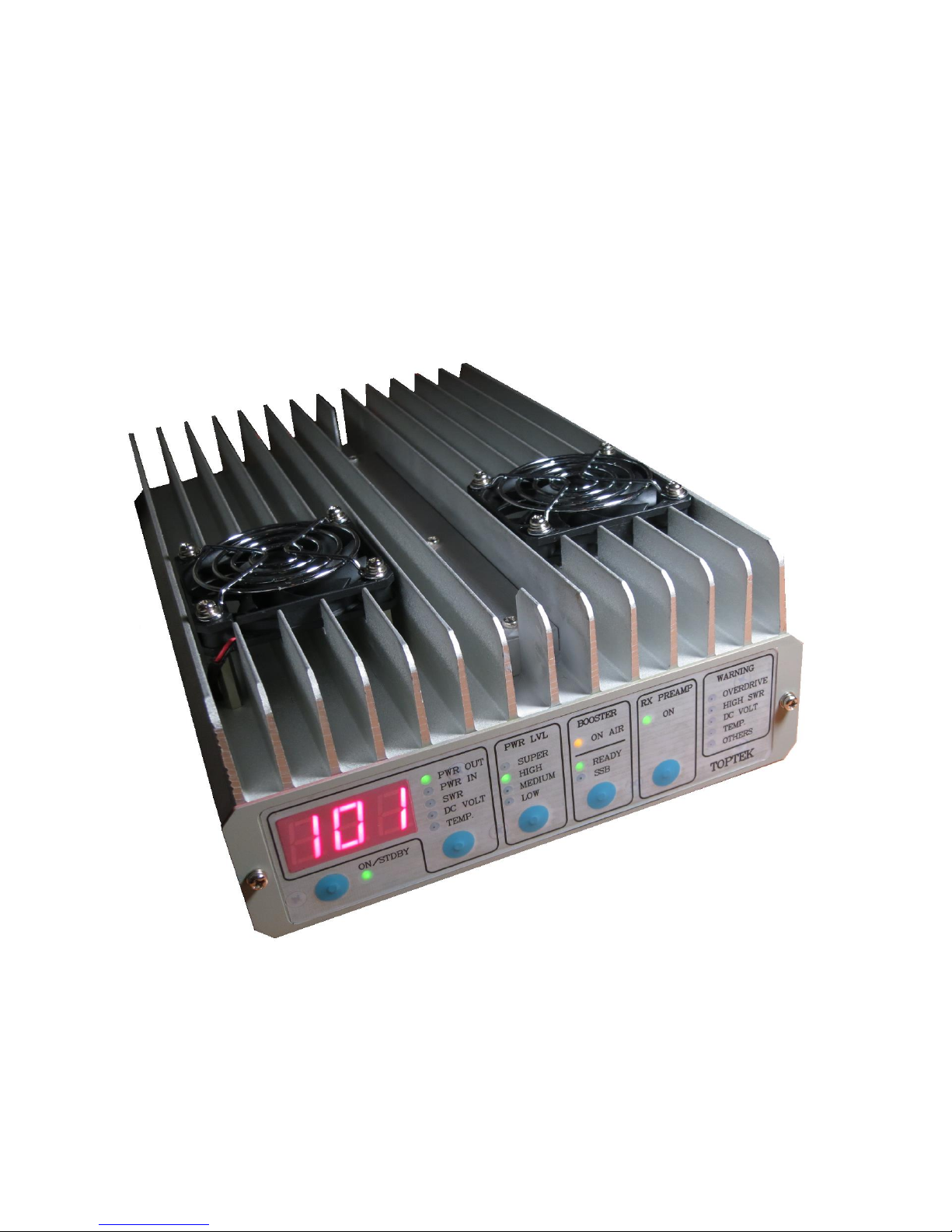
PA-100U-5 is 2-stage UHF power amplifier, capable of delivering 100Watt RF output from
less then 2Watt of drive power. Driver stare uses single MOS-FET. Final stage uses 2 MOS-
FETs in push-pull configuration.
Receiver Low Noise Amplifier (LNA) is provided, to minimize noise figure degradation
caused by transceiver-to-amplifier cable loss. Band-pass filter to prevent blocking by out-of-
band signals is included.
Multi-function, digital meter allows instant verification of: Output RF power, Input RF
power, antenna SWR, DC supply voltage and chassis temperature.
Multipath Automatic Level Control (ALC) provides reliable output power control and
amplifier damage protection.
Output power is selectable between 4 available, pre-programmed levels.
Multiple protection features enhance system reliability: Over-drive, High SWR, DC Voltage
out of range, Over-temperature, Out of band operation.
Automatically enabled, silent fans are installed to enhance amplifier cooling.
Provision for digital remote control is available.

Tentative release: 2016-06-21
SPECIFICATIONS
Frequency range: 430MHz –460 MHz
Mode: Selectable AM/FM or SSB
RF output power: Selectable in 4 steps:
LOW: 25Watt
MEDIUM: 50 Watt
HIGH: 100 Watt
SUPER: >100 Watt (limited to 120 Watt typ.)
RF input power: Maximum: 8 Watt
(Exceeding maximum limit will trigger OVERDRIVE
protection, PA operation will be denied)
Recommended: 2Watt <Pin <5 Watt
RF input power,
PA not active (bypass): Maximum: 50 Watt, <50% duty cycle
DC supply voltage: Minimum: 10.5 V
Maximum: 14.5 V
(Outside above limits, PA operation will be denied)
Recommended: 13.6 V
DC supply current
during transmission: Maximum: 24 Amp
Typical (f=450 MHz):
LOW: 9.5 Amp
MEDIUM: 13.5 Amp
HIGH: 19.5 Amp
SUPER: 21.0 Amp

Tentative release: 2016-06-21
Bypass mode insertion
loss: typ. 1 dB
RX preamplifier gain: typ. 10 dB @ 450 MHz
RX preamplifier noise fig.: typ. 3.5 dB @ 450 MHz
RF connectors type: N-50
Dimensions 183 (W) * 78 (H) * 280 (D) mm
Weight 2.8 Kgs .
Tentative release: 2016-06-21
OPERATION
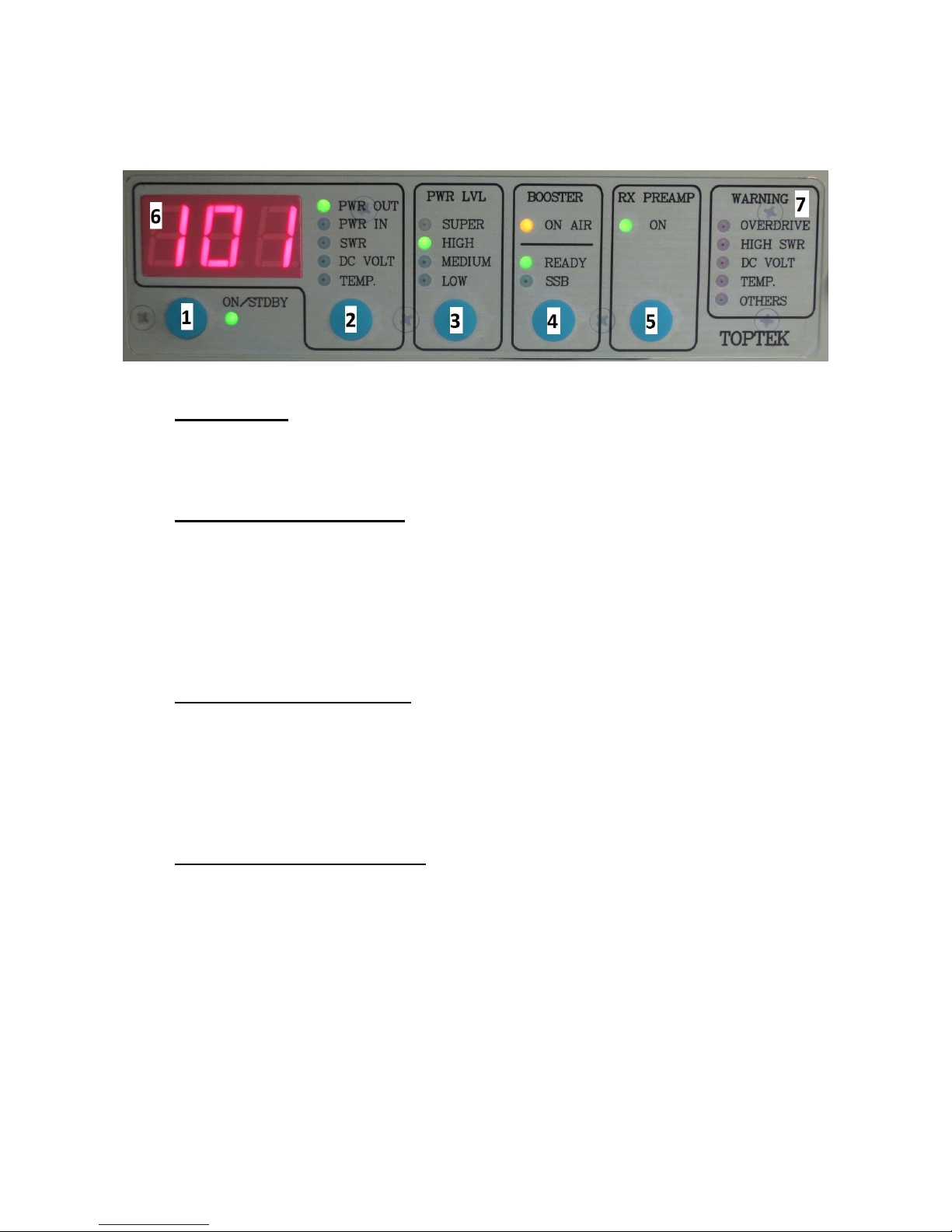
PA-100U-5 front panel layout:
[1] ON/STANDBY
Button toggles between ON mode (PA100U is powered up, meter and annuciators are lit)
and STANDBY mode (PA100U sleeps, display is blank, ON/STDBY LED flashes).
[2] METER MODE SELECTION
Button toggles between various modes of meter [6] operation:
PWR OUT Output RF power measurement (Watt)
PWR IN Input RF power measurement (Watt)
SWR Load SWR measurement (Unitless)
DC VOLT DC voltage measurement (Volts)
TEMP. Chassis temperature measurement (Degrees Celsius)
[3] POWER LEVEL SELECTION
Button toggles between various power levels:
LOW Pmax=25Watt**
MEDIUM Pmax=50Watt**
HIGH Pmax=100Watt**
SUPER 100Watt**<Pmax<appr.120Watt**
[4] BOOSTER MODE SELECTION
Button toggles between 3 modes of power amplifier operation
IDLE READY and SSB LEDs are blank.
Power amplifiers will not go to TX mode upon detecting input drive
signal.
READY Power amplifier is ready for TX mode.
READY+SSB Power amplifier is ready for TX mode and SSB modulation.

Tentative release: 2016-06-21
[5] RX PREAMPLIFIER ON/OFF
Button toggless receiver preamplifier on or off.
[6] MULTI-FUNCTION DIGITAL METER
-Normally, meter displays measured parameter value. In SSB mode, meter works in PEP
measurement mode, offering fast rise times and sluggish decay.
-If value cannot be measured, due to insufficient level (happens to SWR),
„---” is dispalyed.
-If value cannot be measured, due to excessive level (happens to PWR IN)
„---” is displayed and flashing.
-Immediately after switching from STANDBY to ON (button [1]), meter animates (scrolls)
the information about RF power and center frequency: „Po.100 Fr.430-460”
[7] WARNING LEDs
OVERDRIVE Indicates excessive drive power (>8W**)
HIGH SWR Indicates excessive SWR. Depending on actual SWR value,
TX mode will be denied or allowed with limited output power.
DC VOLT Indicates DC voltage being outside operating range
(10.5V** to 14.5V**). TX mode will be denied.
TEMP. Indicates excessive chassis temperature (T>60** deg.). TX will be
denied.
OTHERS Indicates other abnormal conditions, such as attempt to operate as
signifficantly lower frequency (connecting VHF transceiver),final
stage gain being too low, others. TX mode will be denied.
(**) Thresholds are programmed at the factory and may be changed without notice.
Table of contents


