Toika Eeva ES User manual

1
Assembly Manual
Toika Eeva ES, computer-assist loom
To open your crate, snap o the metal straps using a hacksaw or a pair of metal snips. Then using a crow-
bar or another appropriate tool, li the cover o the crate. You'll see all of your parts neatly packed.
Incidentally, many of our customers save the crate. It's birch plywood and makes great shelves, tables and
other neat stu.
Remove all the contents of the crate and get everything into your studio or the space where the loom will
be set up. You should have all of the following:
2 castle sides
1 warp beam
1 cloth beam
3 idencal pieces that measure the width of your loom: these are the back beam, breast beam and knee
beam and they are interchangeable.
1 2x6 (approx.) with holes; the ends are narrower and have slots - lower back cross piece
1 2x5 (approx.) the ends are narrower and have slots - lower front cross piece
1 2x4 (approx.) the ends are narrower and have slots—upper back cross piece
6 wedges (with Liisa, you'll have 10 wedges)
1 computer assist box
2 rails (approximately 1x4 each) for aaching control box to top of loom
Wooden sha bars – 2 for each sha
Metal sha rods - 2 for each sha
Bag of pulleys – 3 for each sha
3 long metal rods with holes in one end
Front crank
Rear warp beam crank
Pre cut texsolv e up cords – 1 for each sha
Texsolv heddles
Reed
Parts for your beater assembly
boom reed holder
beater cap
2 at sides with screw holes in the top and a vercal slot at the boom
a long 2 x 2 piece with aached pointed pivot points at both ends.
Bag of anchor pins
Bag of small parts including bolts, o-rings, etc
Bench kit
2
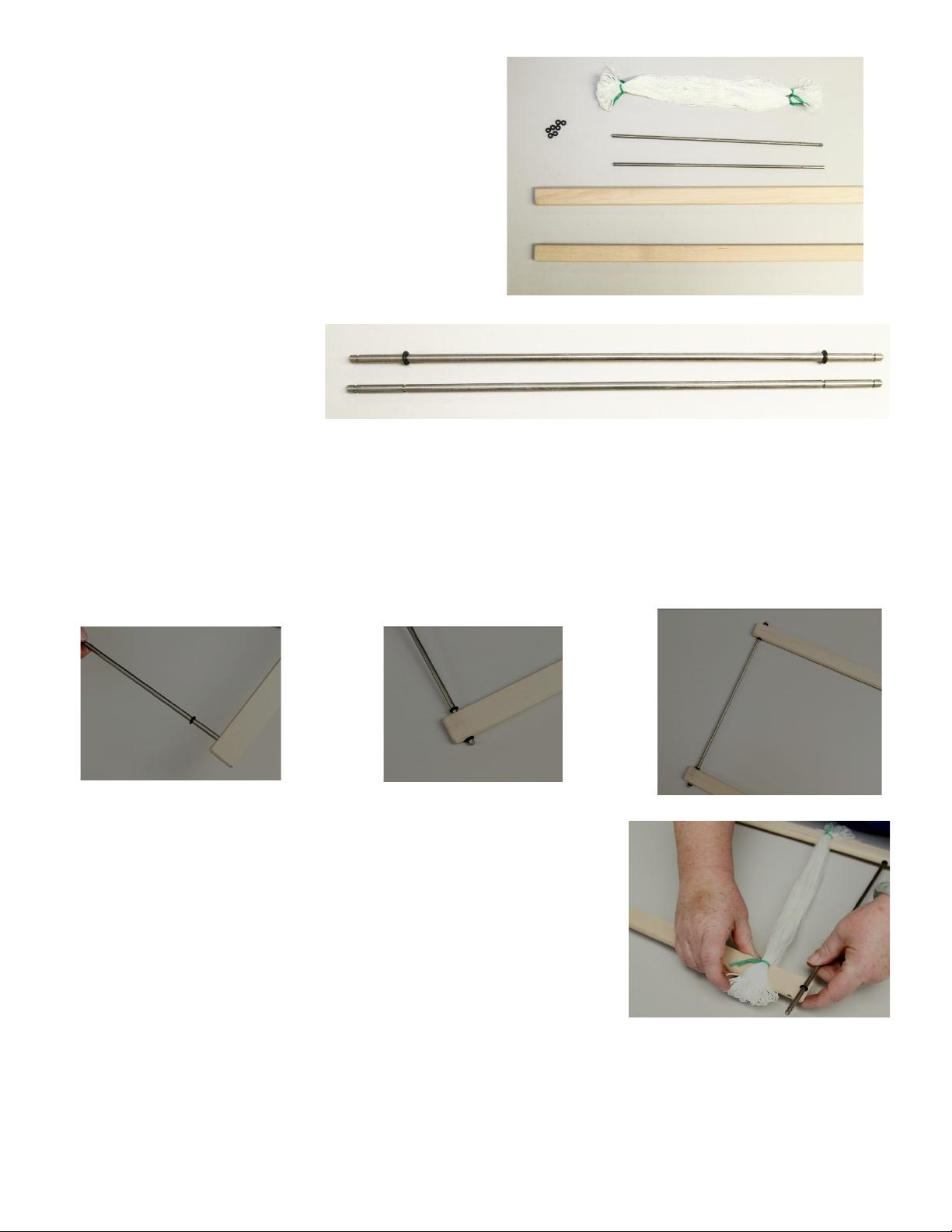
Assembling the shas
The parts you'll need are the sha bars, the
small metal rods, texsolv heddles, and the bag of
lile “O” rings.
Even though the sha bars are smooth sanded
at the factory, many weavers prefer to do a lile
extra sanding to help the heddles slide more
smoothly. If you are so inclined, lightly sand the
sha bars with some very ne sand paper.
Look at the metal rods and you
will note that each rod has two
indentaons on each end. Take an
O-ring, slide it on the end of the
rod and roll it down to the inner
indentaon. Turn the rod over and do the same for the other side – slide an O ring down to the inner inden-
taon.
Do this for each of the metal rods.
Now take a sha bar and insert the end of the rod into the hole at the end of the bar. Slide another O-ring
into the sha bar, leng it sit in the second indentaon. This secures the rod onto the sha bar. Now take
another sha bar and slide it onto the other end of the metal rod and secure that with an O-ring. At this point
the sha will sll be open at one end.
The next step is to take a bundle of Texsolv heddles and slide the heddle
openings onto the open ends of the two parallel sha bars. Slide them all
the way over to where the metal rod connects the two bars.
Take another metal rod and push the ends through the heddle bar holes
from the inside at the open end of the sha. Now secure the metal bar
against the heddle bar with an O-ring in the outer indentaon on top and
boom of the rod. You now have a complete sha.
Build the rest of the shas for your unit by repeang the above steps.
The loops that connect each of the heddles should be cut apart to allow the
heddles to move independently of each other. This is easiest to do at this stage
before the shas are hung.

3
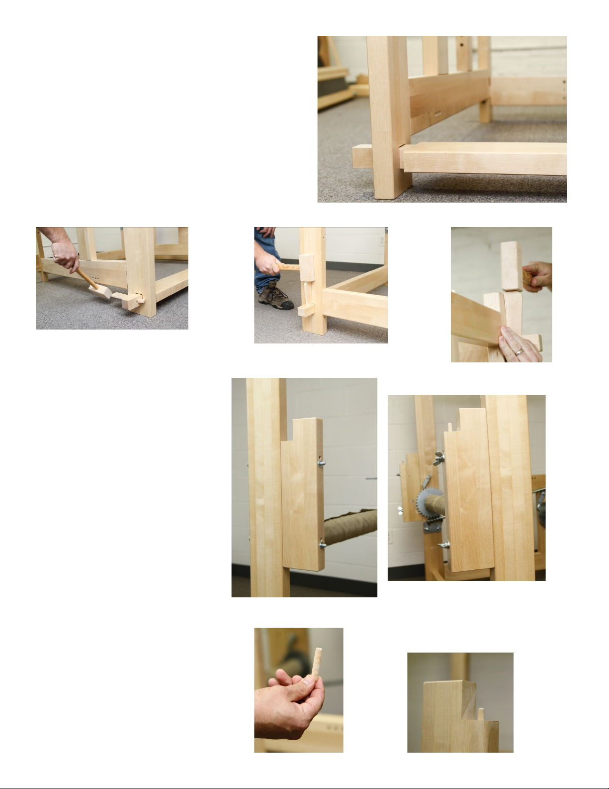
5. Take the 2x4 piece and insert an end into the hole in
the upper rear of the castle. Again, the narrow side
should be parallel to the oor. Insert another wedge in-
to the end of that cross piece.
3. The end of the cross piece has a slot; put one of the wedges
through the hole in that slot. Note that the wedge has one at
side and one angular one; the at side should be next to the
loom. Later this wedge will be hammered into place, for now it
can just sit there.
4. Next take the 2 x 6 without the holes and place it into the
hole at the boom near the front of the loom. This piece
should be set in with the wide side parallel to the oor. In-
sert another wedge into the slot at the end of that piece;
the wedge should be inserted back to front, with the at
edge against the loom.
Building the Main Frame
2. Find the 2x6 with all the lile holes in in it
and insert the end into the square hole at
the boom rear of the castle side. This cross
beam should be installed so that the narrow
side is parallel to the oor.
1. Stand up the right castle side -
the one with the cog wheel mecha-
nism mounted on the inside. Lean
the side against the wall or, if you
have two people, one person can
hold it.
1
2
3
4
5

4
The other beam is the cloth beam and it will slot into the wooden upright towards the front of the loom
(there is a metal plate here as well).
Important - before you set your cloth
beam in place, slip the round end of
your crank over the axle of the beam. The ratchet part of your
crank should be above
the crank handle.
Note: the plate with the worm gear should be in the
upper posion and ghtened in place (it somemes
loosens during shipping) so that the gear and teeth are
engaged. In addion, the pawl above the gear should
be vercal and ghtened so it does not touch the
gear. You only use the pawl if the gear is disengaged.
The worm gear is also called the cogwheel.
Now examine the two beams with the gears on the end. One has a threaded end (g 1) That is your
warp beam and should go through the hole with a metal plate on the back of the frame about two and half
feet up from the oor (g 2).
Fig 1
Fig 2
5
Okay, now you really need that second person.
Take the le castle side and align the le ends of all
of the cross pieces you installed on the right castle
side with the corresponding holes on the le side.
Push them all through.
Take your last three wedges and place them in the
ends of the three cross pieces. Now you can use
your mallet to hammer in the wedges securely.
Installing back, breast and
knee beams.
For packing purposes, the blocks
that hold the back beam are installed
inside the castle sides (g 3)
Unbolt these blocks and install
them on the back of the castle sides
(g 4). There are 2 pairs of holes in
the castle side and the bolts will go
through the lower hole of each pair.
Tighten the wingnuts and be sure
that the back beam slots are on the
same level as those that hold the
breast beam.
Install the small wooden dowels
into the holes in the blocks for the
back beam and in the side frames
where each of the beams will sit.
A tap with the mallet will set
these in place.
Fig 4
Fig 3
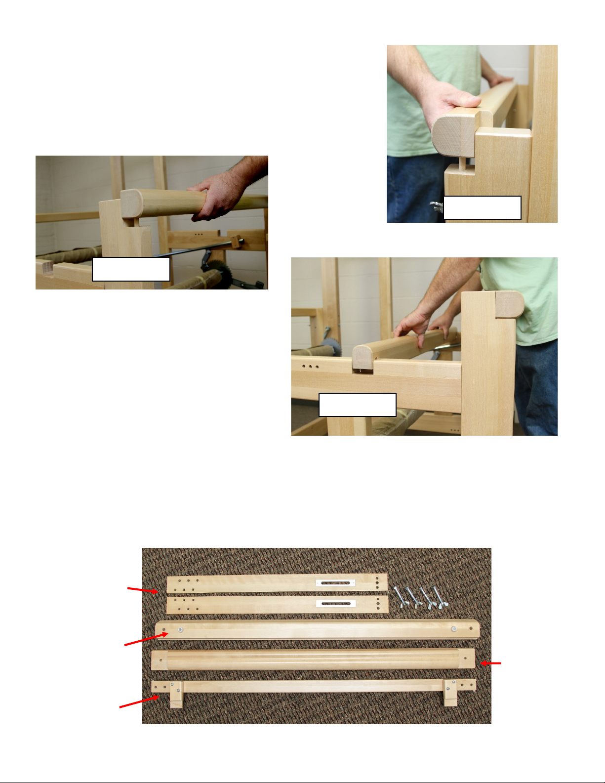
6
Slip the back beam onto the support blocks, the breast beam
on the front of the loom and the knee beam into the slots
about two feet into the loom from the front. Because these
beams are idencal, if one of them is ght you can swap them
around to nd the best t. You can also rub the dowels with a
bar of soap to help it slide in.
Breast beam
Back beam
Knee beam
Leveling the loom
In order for the control mechanism to funcon
properly, the loom must sit level on the oor.
Check this by placing a level on the top edge of
each side frame to check the back-to-front level.
Place the level on the one of the rails that hold
the control box to check for side-to-side level.
Use shims under the corners as necessary to cor-
rect any problems.
Assembling the Overhead Beater
2 side pieces
Beater boom - has
rubber bumpers Beater cap
Top connector

7
Assembling the Overhead Beater cont’d
Aach the beater boom to the sides by
lining up the dowels on the beater boom
with the holes on the side piece. Note that
the rubber bumpers on the beater face
forward and the metal slides on the side
pieces face the back. Tap the side piece to
push onto the dowels. Fasten with a long
bolt and wingnut—the wingnut should be
on the back side.
Back side Front side
Aach the beater cap to the sides with
bolts and wingnuts, fastening near the
top of the metal slides with the
wingnuts facing the back. The cap can
be moved up and down to accommo-
date dierent height reeds.
The top connector aaches to the side pieces with
bolts and wingnuts (wingnuts can face either front
or back). We recommend using the 2nd or 3rd hole
down to start, then adjusng as needed once you
have your rst warp on. (see ‘Leveling the rst
warp’ on page 13).
8
Assembling the Overhead Beater cont’d
The beater will sit in the beater mounts, which
are on the front uprights and look like a ridged
block. Aer the shas have been hung, you can
li the beater up and drop it into the beater
mount. Experiment with which posion in the
ridges is best for your arm length and shed size.
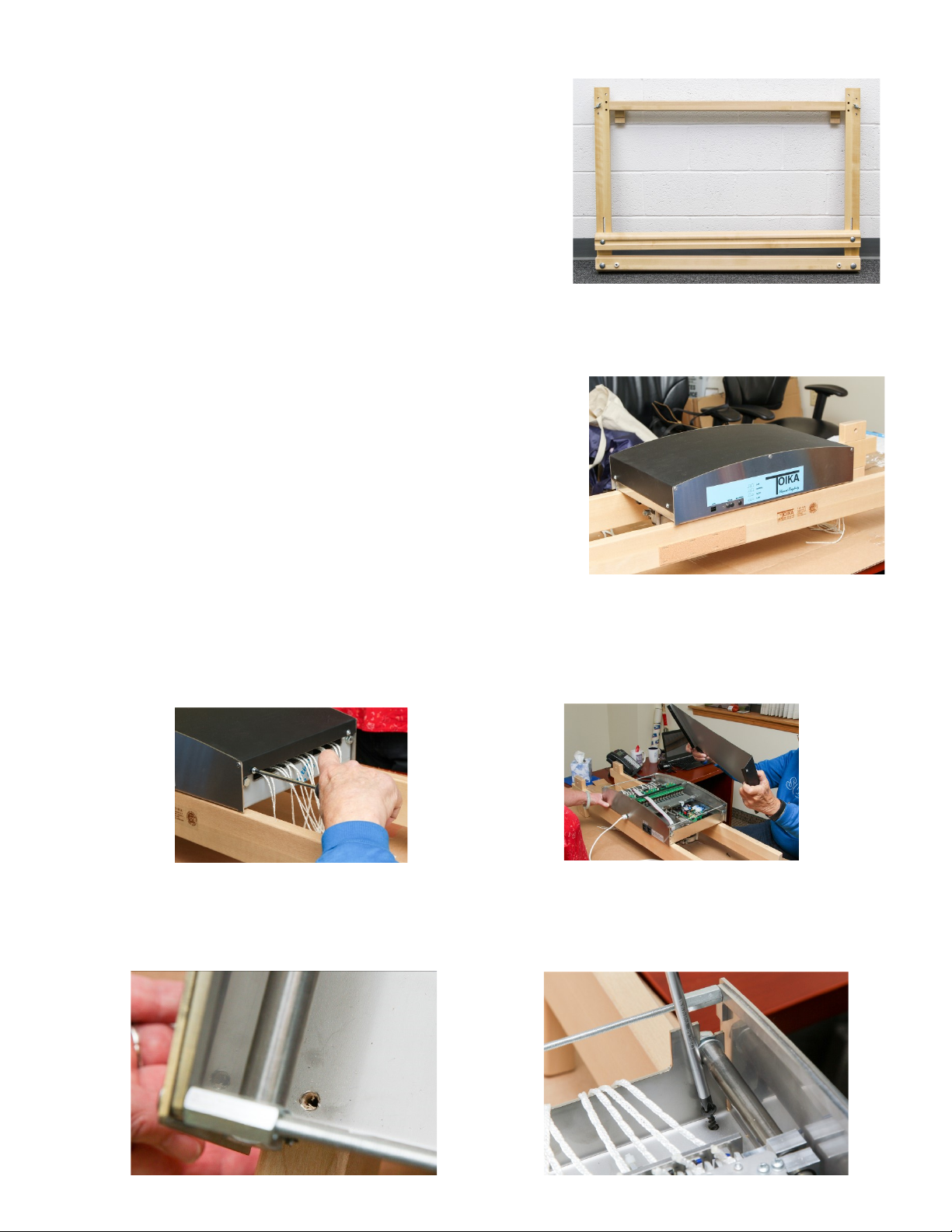
Mounng the control box on the rails
This is best with 2 people as you will need to balance the box on
the rails while aaching it. Start by placing the 2 rails on a at
surface and hold them steady while placing the box carefully on
top. The front rail and the front of the box have the Toika logo
on them.
Remove the lid by loosening the 2 screws at each end of the box. The screws will stay axed to the lid. Li
the lid and set aside
Line up the holes in the 4 corners of the box with the holes in the rails. Screw rmly in place.

9
Installing the computer assist box
Now you are ready to install the box on top of the
loom. Locate four 10mm x 40mm dowels in your
parts bag, then look at the top of the side frames
to nd the posion for the rails before liing it up.
There is a set of holes immediately behind the
beater mounts; the dowels for the front rail will t
into second hole from the end (away from the
beater).
The second dowel will go into one of the set of 3
holes furthest back on the side frame. Measure
the distance between the 2 rails with the box
aached and use that measurement to determine
which of those 3 holes to use and insert the dowel.
Each side frame will have 2 dowels, one for the
front rail and one for the back rail.
Two people can then li the rails and carry
it high over the frame sides so that the
notches in the rails slip over the frame
sides and the holes in the rails line up with
the dowels in the side frames.
When you have all four sides of the rails
lined up with the four dowels, push the
rails down onto the side frames. Your con-
trol box is now secure.

10
Building the Bench
In the bench kit you'll nd a large board with notches in the two sides, two “T” shaped bench sides, a 2x4
piece with dowels on each end, two long barrel bolt assemblies, and two slim bolts with wing nuts. You'll
also nd two heavy rods with holes drilled at one end.
First take the “T side and the 2x4 piece. Push the 2x4 piece into the holes on the side of the “T” piece. The
holes in the 2x4 piece should face downwards toward the T. Now do the same for the other T piece. Now
take the barrel bolt assembly and place the round nut into the large hole underneath the 2x4. The slot on
the nut should be parallel with the sides of the 2x4 piece. Insert the bolt through the hole on the outside of
the “T” shaped leg and ghten it with the wrench provided. Do the same procedure for the other side.
Now take the heavy rods and slide them through one set of the large holes at the top of the T shaped
legs. One rod should have its hole at the far side and the other rod should have its hole at the near
side. Now look at the seat and you will see one hole at each end. Align these holes with the holes in the
metal rods, insert the thin bolts and secure with a wing nut on the boom. Hammer the tops of the bolts to
have them indent themselves into the body of the seat. Note that you have four sets of holes in the bench
legs; this will allow you to adjust the seat to your comfort level.
Hanging the shas (text from video tutorial)
Installing the pulleys
To install the pulleys, nd the three long rods with holes in the ends, a bag of pulleys and three coer pins.
The rails have three blocks preinstalled – one on the le underside, one on the right underside, and one on
the right top. Note that for each set of blocks, the back ones are drilled all the way through and the front ones
are drilled partway through from the back.
First, count out 3 piles of 16, 24 or 32 pulleys depending on the number of shas you have. Then take one pile
and start on the le underside. Take a metal rod and slide the end without the hole through the hole in the
back block from back to front. As the rod goes through the hole, slide the pulleys on the rod between the
blocks. Note that each pulley has a rise on one side. When you slide on the pulleys make sure the rises face
the same direcon. Aer you get all the pulleys onto the rod, push the rod end into the hole in the front pul-
ley. Aer you push rod all the way thought, you'll see that the lile hole drilled into the rod will be inside of
the rear block. Slip the straight side of the coer pin through the hole and secure it. Your pulleys are now
secured for that set of blocks.
Repeat the same procedure for the other two sets of blocks.
Video Tutorial - hanging the shas and connecng the control box
Follow this link for the video: hps://www.youtube.com/watch?v=ZMFdoGIMEtA
Table of contents
Popular Weaving Tools & Accessories manuals by other brands


Ashford
Ashford SPINNING WHEEL MAINTENANCE KIT instructions

Ashford
Ashford RIGID HEDDLE TABLE STAND instructions

Ashford
Ashford SampleIt Loom Stand instructions

Ashford
Ashford Lazy Kate Super Jumbo quick start guide

Ashford
Ashford PACKER BRUSH instructions

Ashford
Ashford TREADLE KIT FOR TABLE LOOM STAND instructions