Toa AM-CF1B User guide

SETUP MANUAL
Thank you for purchasing TOA’s Integrated Audio Collaboration System.
Please carefully follow the instructions in this manual to ensure long, trouble-free use of your equipment.
INTEGRATED AUDIO COLLABORATION SYSTEM
AM-CF1B, AM-CF1W

2
TABLE OF CONTENTS
1. OVERVIEW OF SYSTEM SETTINGS ................................................... 3
2. SYSTEM REQUIREMENTS ........................................................................ 3
3. CONNECTIONS ................................................................................................. 4
4. SETTINGS ............................................................................................................. 5
4.1. Settings Screen Switching ..................................................................................... 5
4.2. Mixer Screen Settings ........................................................................................... 5
4.3. How to Set the Audio Settings Screen .................................................................. 9
4.4. Preset Data Loading and Storage Screen Settings ............................................ 11
4.5. Configuration Settings ........................................................................................ 12

3
1. OVERVIEW OF SYSTEM SETTINGS
Connecting the AM-CF1 unit to a PC by way of a LAN cable allows the following function settings and
maintenance to be performed using the PC’s browser:
[Unit Settings]
• Network settings
• Clock settings
• User account settings
• Bluetooth® name settings
• Key lock setting
[Operation Settings]
• Volume adjustment and current value conrmation of various audio inputs and outputs
• EQ parameter adjustment
• Settings for microphone sound collection
• Echo and noise cancellation settings
• Operation settings for control input and output terminals by contact input and output signals
• Operation setting for the multifunction indicators
• Saving and reading of the above setting data
[Maintenance Function]
• Firmware update
2. SYSTEM REQUIREMENTS
PC hardware requirements are as follows:
Display 1366 x 768 resolution or higher
Conrmed PC operation environments are as follows:
OS Windows 10, 64-bit
macOS 10.4.3 Mojave
Browser Google Chrome 72.0.3626.81, Safari 12.0.3

4
3. CONNECTIONS
Step 1. Start up the web browser and enter “Unit’s IP address” in the address eld.
Example: 192.16 8.14.1
The login screen is displayed.
Tip: The IP address is factory-preset to “192.168.14.1”.
Step 2. Enter a user name and a password.
The mixer screen is displayed.
Note
Do not launch multiple web browsers at the same time.
Tip
Default user name and password are as follows:
User name: amcf1
Password: amcf1guest

5
1
2
3
4
4. SETTINGS
4.1. Settings Screen Switching
Click the following screen name or icon to switch the settings screen to the desired screen. Perform necessary
settings on each screen.
Screen Name or Icon Setting Contents
1
Mixer screen (Mixer) Used to set input and output gains, etc. Equalizer settings are possible
for both speaker and AUX outputs. (See below.)
2
Audio settings screen (Audio
Setting)
Used to set microphone collection sound parameters, echo cancellers
and noise cancellers. (See p. 9.)
3
Preset data loading and storage
screen (Preset Load/Store)
Used to perform settings regarding the methods of loading and storing
preset data. (See p. 11.)
4
Conguration icon Used to perform settings related to networks, contact control/front
panel LED indication and day and time/rmware update. (See p. 12.)
4.2. Mixer Screen Settings
12
3
A
B
C
D
E
F
G
H
I
J
K
(1) Input signal adjustment section (INPUT)
Perform settings related to input signals.
The following four input types are made available:
USB
Bluetooth
CODEC
AUX

6
Name Description
AInput gain display Input gains are displayed numerically.
Numerical values can be changed with the arrows to the right of each value.
Initial setting: 0 dB
Tip: Linked to faders (C).
BInput level indicators Display input levels.
CFaders Used to change input gains.
Tip: Linked to input gain display (A).
DMute button Click to mute corresponding input. Clicking again returns input to the previous
level.
EReset button Click to return all input adjustment settings to their initial settings.
(2) Output signal adjustment section (OUTPUT)
Perform settings related to output signals.
Settings for the following ve types of output can be performed:
Speaker
USB
Bluetooth
CODEC
AUX
Name Description
F EQ button Performs equalization on both speaker and AUX outputs. Clicking this button
opens the Equalizer Screen. (See p. 7.)
GOutput gain display Output gains are displayed numerically. Numerical values can be changed
using the arrows to the right of each value.
Initial setting as follows:
Speaker, USB, CODEC, AUX: 0 dB
Bluetooth: –20 dB
Tip: Linked to faders (I).
H Output level indicators Display output levels.
IFaders Used to adjust output gains.
Tip: Linked to output gain display (G).
JMute button Click to mute corresponding output. Clicking again returns output to the
previous level.
KReset button Click to return all output adjustment settings to their initial settings.
(3) APPLY button
Click this button after all settings on this screen are completed. Setting contents are applied.

7
[Equalizer Settings]
Clicking the EQ button (see the previous page) displays the equalizer screen.
Both speaker and AUX outputs allow equalizer settings on 5 points and PEQ (parametric equalizer) parameters
can be set on all of the 5 points. In addition, PEQ or HPF (high-pass lter) settings can be performed on the
leftmost point, and PEQ or LPF (low-pass lter) settings can be performed on the ringhtmost point.
(Example: Speaker Output Equalizer Screen)
(1) Back icon
Clicking this icon returns the screen to the Mixer Screen.
(2) EQ curve display section
EQ curves are displayed depending on parameter settings.
(3) PEQ/HPF setting section
Used to set PEQ or HPF parameters.
Name Description
APEQ/HPF selection Select the parameter type (PEQ or HPF).
Initial setting as follows:
Speaker output: HPF
AUX output: PEQ
BParameter settings Set parameters for Freq (frequency), Gain and Q.
The setting range and initial settings are shown in the table below.
Note: Gain and Q cannot be set if HPF is selected in the PEQ/HPF selection.
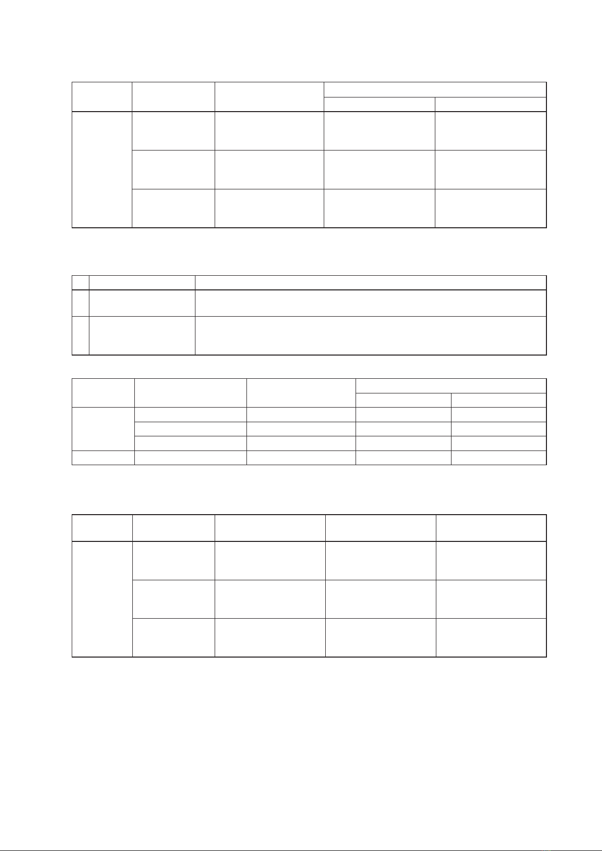
[Setting Ranges and Initial Settings]
Setting Item Setting Contents Setting Range Initial Setting
Speaker Output AUX Output
PEQ Freq (Hz) 20 to 20000 300 200
Gain (dB) –15 to 15, 0.5 dB steps 0 0
Q0.267 to 69.249 0.718 4.318
HPF Freq (Hz) 20 to 20000 300 200
1
2
3 4 5
6
A
BC D E
F
G
7
8
(4) PEQ setting section
Set Frequency, Gain and Q parameters.
The setting range and initial settings are as shown in the table below:
Setting Item Setting Contents Setting Range Initial Setting
Speaker Output AUX Output
PEQ Freq (Hz) 20 to 20000 C: 300
D: 600
E: 4000
C: 630
D: 1600
E: 4000
Gain (dB) –15 to 15, 0.5 dB steps C: –6
D: –3
E: 8
C: 0
D: 0
E: 0
Q0.267 to 69.249 C: 4.318
D: 4.318
E: 2.145
C: 4.318
D: 4.318
E: 4.318
(5) PEQ/LPF setting section
Used to set PEQ or LPF parameters.
Name Description
APEQ/HPF selection Select the parameter type (PEQ or LPF).
Initial setting: PEQ
BParameter settings Set parameters for Freq (frequency), Gain and Q.
The setting range and initial settings are shown in the table below.
Note: Gain and Q cannot be set if LPF is selected in the PEQ/HLPF selection.
[Setting Ranges and Initial Settings]
Setting Item Setting Contents Setting Range Initial Setting
Speaker Output AUX Output
PEQ Freq (Hz) 20 to 20000 10000 10000
Gain (dB) –15 to 15, 0.5 dB steps 0 0
Q0.267 to 69.249 4.318 4.318
HPF Freq (Hz) 20 to 20000 10000 10000
(6) Reset button
Click this button to change the values (3) – (5) of speaker output and AUX output, respectively, as follows:
Setting Item Setting Contents (3) PEQ/HPF setting
section (4) PEQ setting section (5) PEQ/LPF setting
section
PEQ Freq (Hz) 200 C: 630
D: 1600
E: 4000
10000
Gain (dB) 0 C: 0
D: 0
E: 0
0
Q4.318 C: 4.318
D: 4.318
E: 4.318
4.318
(7) APPLY button
Click this button after all settings on this screen are completed. Setting contents are applied.

9
4.3. How to Set the Audio Settings Screen
Perform settings related to microphone sound collection.
(1) Tracking Field
Set the range of sound source tracking with the microphone position (AM-CF1) as a reference. Use distances
to the left and right from the center of the microphone position (AM-CF1) and the distance directly in front
of the microphone to set the range.
Name Description
ARange display The sound source tracking range is displayed in orange.
BX1 axis setting Set the distance from the microphone position in the direction of the X1 axis.
Setting range: 0 to 300 cm (0 to 120 inch)
Initial setting: 200 cm (80 inch)
C X2 axis setting Set the distance from the microphone position in the direction of the X2
axis.
Setting range: 0 to 300 cm (0 to 120 inch)
Initial setting: 200 cm (80 inch)
DShortest distance setting Set the shortest distance in front of the microphone position.
Setting range: 20 to 590 cm (8 to 236 inch)
Initial setting: 20 cm (8 inch)
EFarthest distance setting Set the farthest distance in front of the microphone position.
Setting range: 30 to 600 cm (12 to 240 inch)
Initial setting: 400 cm (160 inch)
F Unit selection Click to set the unit of distance to either centimeters (cm) or inches. The
selected unit is displayed in orange.
Initial setting: cm
(2) Tracking Sensitivity
Set the sensitivity to be used to specify a sound source.
Setting range: Low, Mid and High
Initial setting: Mid
1
2
3
4
5
6
A
B
C
D
E
F
GHI
J K

10
(3) Steering Mode
Set whether or not to track a sound source by clicking “Auto” or “Fixed.”
The set mode is displayed in orange.
“Auto”: Select this when tracking the sound source.
“Fixed”: Select this when the sound source position is xed and thus not being tracked.
Initial setting: Auto
(4) Echo Canceller (AEC)
Name Description
GON/OFF switching Turns the [AEC] (Acoustic Echo Canceller) mode ON or OFF.
The selected mode is displayed in orange.
Initial setting: ON
H NLP Level setting Sets the setting level for Non-Linear AEC processing.
Setting range: Low, Mid, High
Initial setting: Mid
I Microphone Gain setting Sets the output volume level of the beam steering microphone.
Setting range: –6, –4, –2, 0, 2, 4 and 6 dB
Initial setting: 0 dB
(5) Noise Cancellation
Name Description
JON/OFF switching Turns the noise cancellation mode ON or OFF.
The selected mode is displayed in orange.
Initial setting: ON
KAttenuation setting Sets the amount of noise attenuation in dB.
Setting range: 6, 9 and 12 dB
Initial setting: 9 dB
(6) APPLY button
Click this button after all settings on this screen are completed. Setting contents are applied.
Other manuals for AM-CF1B
1
This manual suits for next models
1
Table of contents
Other Toa Conference System manuals


Popular Conference System manuals by other brands

Kramer
Kramer VIA GO quick start guide

AVT
AVT MAGIC AC1 Go Configuration guide

ProSoft Technology
ProSoft Technology AN-X4-AB-DHRIO user manual

Sony
Sony PCS-I150 Operation guide

Middle Atlantic Products
Middle Atlantic Products VTC Series instruction sheet

Prentke Romich Company
Prentke Romich Company Vanguard Plus Setting up and using


