Tintometer AQUALYTIC AL15 User manual

AL15
MultiMeter Instrument -
Instruction Manual
pH/ORP DO
CD/TDS
GB

Table of Contents
1. Specifications .............................................................................................1
1.1 General Specifications ................................................................................1
1.2 Electrical Specifications...............................................................................1
2. Front Panel Description...............................................................................4
3. pH/mV Measuring and Calibration Procedure .............................................5
4. Conductivity/TDS Measuring and Calibration Procedure..............................9
5. DO (Dissolved Oxygen) Measuring
and Calibration Procedure ........................................................................12
6. Data Load, Data Record, Data Logger.......................................................16
7. Advanced Adjustment Procedure..............................................................17
7.1 Check Memory Space...............................................................................18
7.2 Clear Memory ..........................................................................................18
7.3 Date/Time Setting ....................................................................................18
7.4 Sample Time Setting ................................................................................19
7.5 Auto Power Off Default Setting................................................................19
7.6 Temp. Unit Default Setting .......................................................................19
7.7 pH Manual Temp. Value Setting................................................................19
7.8 CD Temp. Compensation Factor Setting ...................................................19
7.9 CD ( µS, mS ), TDS ( ppm ) Setting............................................................20
7.10 DO % Salt Compensation Value Setting...................................................20
7.11 DO Height (Altitude) Compensation Value Setting....................................21
7.12 Escape from the Setting function .............................................................21
8. Data Output.............................................................................................31
9. RS232 PC Serial Interface .........................................................................22
10. Battery Replacement ................................................................................23
11. System Reset............................................................................................23
12. Accessories...............................................................................................24
13. Important information for pH electrodes ..................................................25

1
AL15
1. Specifications
1.1 General Specifications
Circuit Custom microprocessor LSI
Display LCD size : 58 mm x 34 mm
Measurement pH / Oxidation Reduction Potential (ORP)
Conductivity/Total Dissolved Solids (TDS)
Dissolved Oxygen (DO)
Temperature
Sampling Time of Data Logger
1 second to 8 hours 59 minutes and 59 seconds
Data-Hold Freeze the display reading.
Speicherfunktion Maximum- und Minimumwerte
Power off • Auto shut off saves battery life; manual shut off possible
by pressing “Power” button for 2 seconds
• Default changeable: auto power off/ manual power off
• With default set at auto power off, power will off
automatically after 10 minutes if no button is pressed.
Data Output RS 232 PC serial interface
Operating Temperature 0 to 50 °C (32 to 122°F) for the instrument (not including
probes)
Operating Humidity Less than 80% rel. humidity
Power Supply • DC 1.5 V with 4 batteries (mignon size; Type AA)
• DC 9 V by adapter input
Power Current • Operation: approx. DC 28 mA
• Clock (power off): approx. DC 1 µA
Weight • instrument 390 g (batteries included)
• with protective covering 620 g
Dimension • instrument: 203 x 76 x 38 mm
• with protective covering: approx.
220 x 125 x 45 mm
1.2 Electrical Specifications (23± 5°C)
A. pH/mV
Measurement pH 0 bis 14 pH
mV -1999 mV to 1999 mV
Input Impedance 1012 ohm
Temperature Compensation
for pH measurement
Manual 0 to 100°C (32 to 212°F)
Automatic
(ATC)
0 to 65°C
(32 bis 149°F) with temperature probe

2AL15
pH Calibration 11 to 3 point calibration using
pH 7 / pH 4 / pH 10 buffer solutions
Three point calibration ensures best linearity and accuracy.
Measurement Range Resolution Accuracy*
pH 0 bis 14 pH 0,01 pH ± (0,02 pH + 2 digits)
mV - 1.999 bis 1.999
mV
1 mV ± (0,5 % pH + 2 digits)
* pH accuracy is based on calibrated meter only.
B. Conductivity
Conductivity probe Carbon rod electrode for long life
Function • Conduction (µS, mS)
• Total Dissolved Solids (ppm)
• Temperature (°C, °F)
Temperature Compensation Automatic from 0 to 60°C (32 – 140 °F),
with temperature compensation factor variable
between 0 to 5 % per °C
Probe Operating Temperature 0 to 60 °C (32 to 140°F)
Probe Dimension Round, 22 mm diameter x 120 mm length
Probe Weight approx. 65 g
Range Measurement Resolution Accuracy
200 µS 0 bis 200,0 µS / cm 0,1 µS / cm ± (2 % F.S.
+ 1 digit)
2 mS 0.2 bis 2,000 mS / cm 0,001 mS / cm
20 mS 2 bis 20,00 mS / cm 0,01 mS / cm
200 mS 20 bis 200,0 mS / cm 0,1 mS / cm
F.S. = Full Scale

3
AL15
C. TDS (Total Dissolved Solids)
Range Measurement Resolution Accuracy
200 ppm 0 bis 132 ppm 0,1 ppm ± (2 % F.S. + 1 Stelle)
2.000 ppm 132 bis 1.320 ppm 1 ppm
20.000 ppm 1.320 bis 13.200 ppm 10 ppm
200.000 ppm 13.200 bis 132.000 ppm 100 ppm
F.S. = Full Scale
D. Temperature
Function Measurement Resolution Accuracy
°C 0 °C bis 60 °C 0,1 °C ± 0,8 °C
°F 32 °F bis 140 °F 0,1 °F ± 1,5 °F
E. Dissolved oxygen
Oxygen Probe Polarographic type oxygen probe
Probe Compensation
and Adjustment
Temperature 0 to 50°C, automatic,
(3 to 122 °F)
Salt 0 to 39 % Salt
Height 0 to 8900 meter
Probe Weight approx. 195 g
Probe Size Round, 190 mm length x 28 mm diameter
Measurement Range Resolution Accuracy (23 ± 5°C)
Dissolved Oxygen 0 to 20.0 mg/L 0.1 mg/L O2± 0.4 mg/L O2
Oxygen in Air 0 to 100 % 0.1 % O2± 0.7 % O2

4AL15
2. Front Panel Description (Fig. A)
A-1 Display
A-2 Power Button
A-3 REC Button (Enter Button)
A-4 HOLD Button (ESC Button)
A-5 Mode Button ( Up Button, Zero Button)
A-6 Function Button (Range Button, Down Button)
A-7 Send Button (Clock Button)
A-8 SET Button (Logger Button)
A-9 Stand
A-10 Battery Compartment Cover
A-11 Battery Cover Screw
A-12 Tripod Fix Nut
A-13 Temp. Socket (pH ATC Socket)
A-14 CD Socket
A-15 DO Socket
A-16 pH Socket (BNC Socket)
A-2
A-3
A-4
A-5
A-6
A-7
A-8
A-1
A-15
A-14
A-13
A-16
A-12
A-9
A-11
A-10

5
AL15
A-17 DC 9V Power Adapter Input Socket
A-18 RS-232 Output Terminal
A-19 System Reset Button
A-20 LCD Brightness Adjust
A-17 A-18 A-19 A-20
DC IN
RS232
RESET
Attention:
Please do not put more than one electrode only into the water sample when
using an instrument that works with various electrodes.
Only start the measurement for which the according electrode is immersed
in the sample.
The meter default settings are as follows:
• The display unit is set to pH.
• The temperature unit is set to °C.
• Manual temperature setting (without ATC probe connection)
• Auto power off.
• Data logger function sampling time: 2 seconds.
3. pH/mV-Messung und Justierung

6AL15
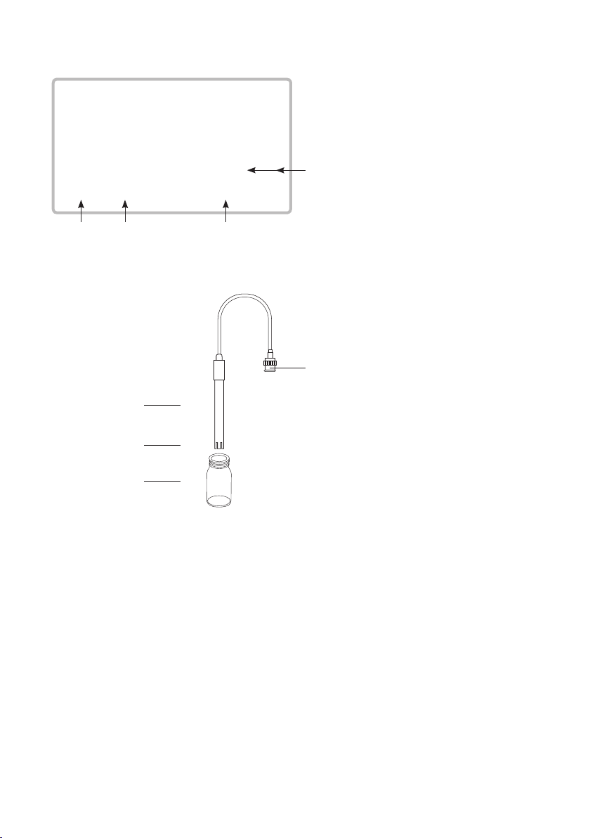
Display layout
Measurement Value
PH
Manual Temp.
25.0 °C
Temp. value
pH or mV
Temp unit
10.00
Manual Temp. or
Auto Temp.
3.1 pH measurement (with manual temperature setting)
1) Attach the pH Electrode by installing the “Probe Plug“ (Fig. B-1) into the “pH
Socket/BNC Socket“ (Page 4, Fig. A-16).
2) Power on the meter by pressing the “Power” button once.
3) Keep pressing the “Mode” button until the display of bottom right shows
“pH“ and “Manual Temp.“ indicator.
4) Adjust the Manual Temp. value exactly to the same temperature
as the
solution. For procedure refer to chapter 7.7, page 19.
5) Remove cap and hold the pH Electrode body (Fig. B-2) and completely im-
merse the “Sensing Head“ (Fig. B-3) in the solution to be measured and gently
swirl the probe.
6) The upper display will show the pH value, the bottom left display will show
the Manual Temp. setting.
Fig. B
B-1
B-2
B-3
B-4

7
AL15
3.2 pH measurement (with ATC , automatic Temperature Compensation)
1) All the procedures are the same as for 3.1 “pH measurement (manual temper-
ature setting)“, except for attachment of a temperature probe by inserting the
plug of the temperature probe into the “Temp. Socket“ (Page 4, Fig. A-13),
and immersing the sensing head of the temperature probe into the measure-
ment solution.
2) The upper display will show the pH value, the bottom left display will show
the Temp. value of the measured solution, and
the bottom right display
will show “Auto Temp.“ as example below:
When not in use the “Electrode Sensing Head“ (Page 6, Fig. B-3) should
always be immersed in water by part-filling the probe cap, (Page 6, Fig.
B-4) and ensuring that the cap is firmly lifted onto the probe. Failure to
do so will reduce probe life.
3.3 mV Measurement
The instrument has a built in mV (millivolt) measurement function, which enables
you to make ion-selective, ORP (oxidation reduction potential), and other precise
mV measurements.
1) Attach the ORP Electrode by installing the “Probe Plug“ of the
ORP electrode
into the “pH Socket/BNC Socket“ (Page 4, Fig. A-16).
2) Power on the meter by pressing the “Power” button once.
3) Keep pressing the “Mode” button until the display at bottom right shows
“PH“ and “Manual Temp.“ indicator.
Press the “Function” button once so that the bottom right display
shows “mV“ .
4) The upper display will show the mV value.
3.4 pH calibration
Calibration - Introduction
An “ideal” pH Electrode generates 0 mV at pH 7.00 (177.4 mV at pH 4). The
meter has been calibrated with signals which simulate the “ideal” pH Electrode
(based on 25°C ambient environment). However not every pH Electrode is as
accurate as the “ideal” one, so calibration procedures are necessary before first
time measurement. In addition to calibration before first time measurement,
users are also recommended to carry out regular calibration to ensure high ac-
curacy measurements.
PH
Auto Temp.
25.0 °C
7.01

8AL15
Required Equipment for Calibration
1) pH Electrode.
2) pH buffer solutions.
Calibration Procedure
1) Attach the pH Electrode by installing the “Probe Plug“ (Page 6, Fig. B-1) into
the “pH Socket/BNC Socket“ (Page 4, Fig. A-16).
2) Power on the meter, set the mode to pH measurement, and the bottom right
display will show “PH“ .
3) Adjust the “Temperature Compensation Value“ to make it the same tempera-
ture as the pH buffer solution.
• Manual temperature compensation value adjustment procedure,
refer to 7-7, page 19.
• Automatic temperature compensation, refer to 3.2, Page 7.
4) Hold the “pH Electrode body“ (Page 6, Fig. B-2) and completely immerse the
“Sensing Head“ (Page 6, Fig. B-3) in the buffer solu
tion and gently swirl the
probe. The display will show the pH value.
5) Press the “REC” button and “HOLD” button at the same time. The display will
show the following screen as an example. Now release.
PH CAL.
^, v Enter : Y
23.5 °C
7.00
6) • If the buffer solution is pH 7.0 (± 1 pH), the upper display will show 7.00
automatically.
• If the buffer solution is pH 4.0 (± 1 pH), the upper display will show 4.00
automatically.
• If the buffer solution is pH 10.0 (± 1 pH), the upper display will show 10.00
automatically.
• If the buffer solution value is beyond pH 7.00, pH 4.00, pH 10.00 (for
example 7.01, 4.02, 10.03) then use
“ ” button, “ ” button to adjust the display value to exactly match the pH
buffer solution value.
7) Press the “Enter” button twice to save the calibration data and finish the
calibration procedure.
Table of contents
Popular Multimeter manuals by other brands

Gossen MetraWatt
Gossen MetraWatt METRAmax 6 operating instructions

PeakTech
PeakTech 4000 Procedure of calibration

YOKOGAWA
YOKOGAWA 90050B user manual

Gossen MetraWatt
Gossen MetraWatt METRALINE DMM16 operating instructions

Fluke
Fluke 8846A Programmer's manual

Tempo Communications
Tempo Communications MM200 instruction manual