TIL TiL-91-DE User manual

VHF/AM
MOBILE TRANSCEIVER
MODEL TiL-91-DE
7 WATT MOBILE SYSTEM NO 910200
(TMS-150)
Installation and
Operating Instructions
Til Document No.
94RE146
Rev. A
October 2001
Technisonic Industries Limited
240 Traders Blvd., Mississauga, Ontario L4Z 1P4 Tel:(905)890-2113 Fax:(905)890-5338
www.til.ca

A Page
WARNING
Do not make physical contact with antenna when transmitter is on. This unit can produce up to 30 watts of
power (depending on configuration) when operated in high power mode.
CAUTION
This unit contains static sensitive devices. Wear a grounded wrist strap and/or conductive gloves when
handling printed circuit boards.
WARRANTY INFORMATION
The Base Stations, Model 91-DE series and Model Til 90-6R series are under warranty for one year from
date of purchase. Failed units caused by defective parts, or workmanship should be returned to:
Technisonic Industries Limited
240 Traders Blvd.
Mississauga, Amherst,NY,USA
Ontario L4Z 1W7
Tel: (905) 890-2113 Tel: (716) 691-0669
Fax: (905) 890-5338

i
TABLE OF CONTENTS
Section Title Page
1 GENERAL DESCRIPTION 1-1
1.1 Introduction 1-1
1.1.1 Purpose of the System 1-1
1.1.2 Modes of Operation 1-2
1.2 Technical Summary 1-9
2 INSTALLATION INFORMATION 2-1
2.1 Introduction 2-1
2.2 Transceiver Location 2-1
2.3 Vehicle Power Supply 2-1
2.4 Power Input Cable Assembly 2-1
2.5 Antenna Assembly 2-2
2.5.1 Antenna Location 2-2
2.5.2 Antenna Installation 2-2
2.6 Mounting Bracket Installation 2-2
2.7 Transceiver Installation 2-2
2.8 Microphone Installation 2-3
2.9 Optional External Loudspeaker or Headphone 2-3
2.9.1 External Loudspeaker 2-3
2.9.2 Headset 2-3
2.10 Operational Check 2-3
3 OPERATING INSTRUCTIONS 3-1
3.1 Introduction 3-1
3.2 Operator's Switches, Controls and Indicators 3-1
3.3 Front Panel Keypad Operation 3-5
3.4 Fixed Channel Frequency Set Up 3-12

ii
LIST OF TABLES
Table No. Title Page
1-1 Leading Particulars 1-9
3-1 Operator's Switches, Controls and Indicators 3-2
3-2 Channel/Function Selector Keypad 3-5
LIST OF ILLUSTRATIONS
Figure No. Title Page
1-1 Transceiver - General View 1-4
1-2 Transceiver with Mounting Bracket - General View 1-5
1-3 Power Input Cable Assembly - General View 1-6
1-4 Microphone Assembly - General View 1-7
1-5 Antenna Assembly - General View 1-8
3-1 Transceiver Front Panel Layout 3-2
3-2 Fixed Channel Jumper Locations 3-11

1-1
SECTION 1
GENERAL DESCRIPTION
1.1 INTRODUCTION
VHF/AM Mobile Transceiver System 910200 (Item No. TMS-150), manufactured by Technisonic
Industries Limited, is a low power VHF/AM Transceiver, complete with Mounting Bracket, Power
Input Cable, Microphone and Antenna.
1.1.1 PURPOSE OF THE SYSTEM
(1) Intended Purpose and Use - The system is intended for installation in airport service
vehicles, such as cars, snowplows, and grass cutters, to allow ground control over such
vehicles while they are negotiating aircraft manouvering areas.
(2) Brief Description of System Units - VHF/AM Mobile Transceiver System 910200 consists
of the following items:
(a) Transceiver Model 91-DE, Part Number 901006-2, Series 1, is a low power VHF/AM
transceiver which operates in simplex and allows quick keypad access and LCD display
of the frequency range 117.975MHz to 138.000MHz with 25kHz channel spacing. The
transceiver operates from a 12 volts dc nominal vehicle power supply (negative ground
only). An optional extra cost dc to dc convertor P/N 863118-1 can be installed in the
transceiver to allow operation from an input supply from 10.8 to 30.0 Vdc. A general
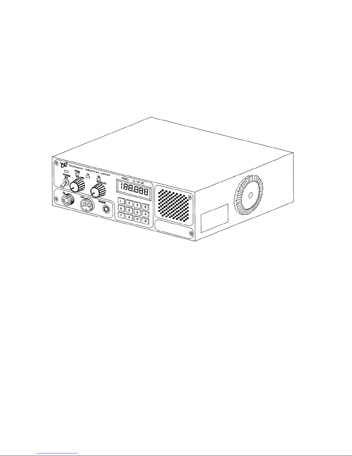
view of the transceiver is given in Figure 1-1. The transceiver is normally located under
the dashboard of a vehicle using a mounting bracket and mounting hardware.
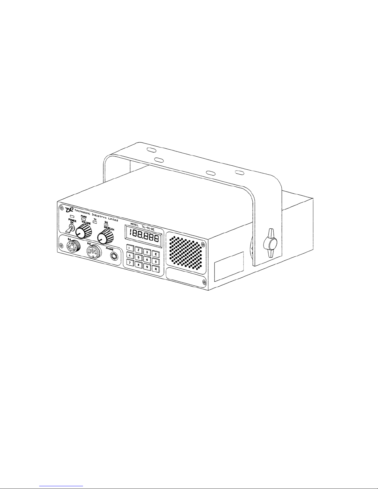
(b) Mounting Bracket, Part Number 913053-1, is a U-shaped aluminum alloy bracket
which, together with items of hardware included in Mounting Hardware Kit P/N 869024-
1, is used to mount the transceiver under the dashboard of a vehicle.
A view of the transceiver with mounting bracket is given in Figure 1-2.
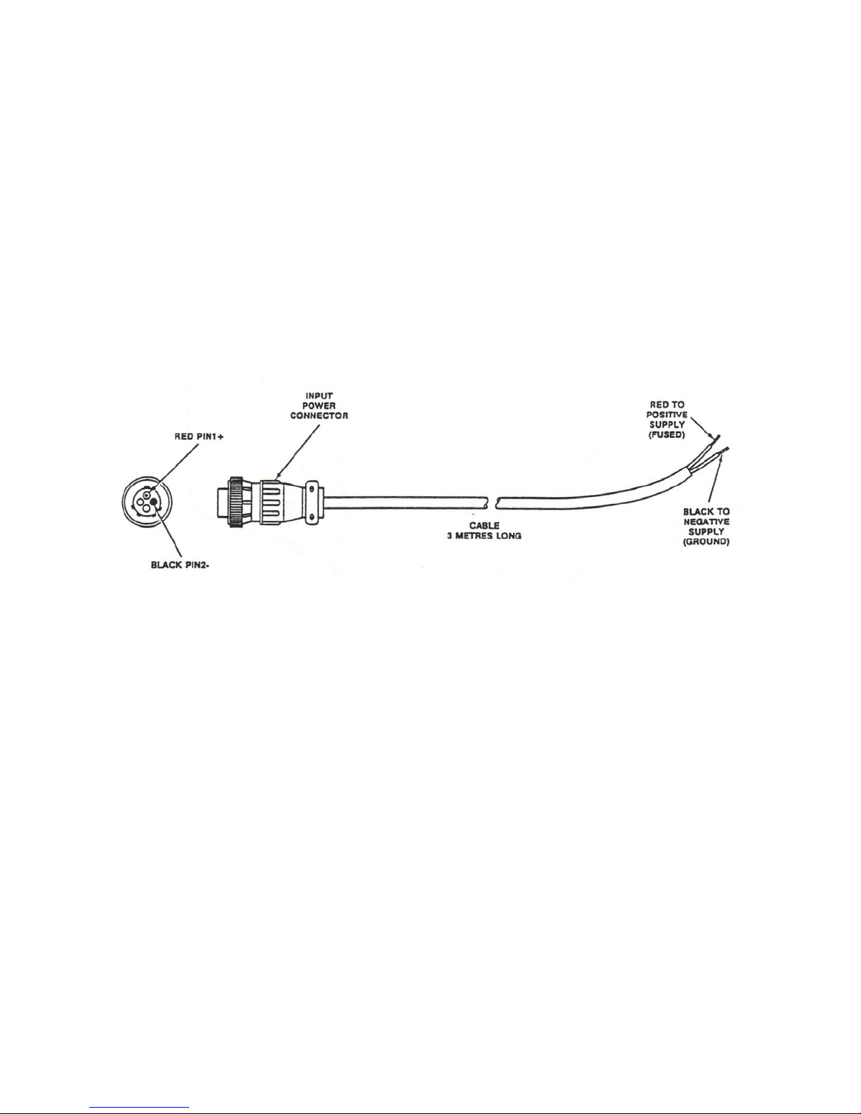
(c) Power Input Cable Assembly, Part Number 863701, is a three-metre length of two-
core cable terminated at one end by a two-pin, female contacts, connector, which mates
with the two-pin, male contacts, connector located at the left-rear of the transceiver. The
unterminated end of the cable is connected to the 12Vdc vehicle power supply negative-
ground during installation.
A view of the cable assembly is given in Figure 1-3.
(d) Microphone Assembly, Part Number 961070-1, consists of a Microphone and a
mounting bracket, P/N RK6MB.
A general view of the microphone assembly is given in Figure 1-4.
The microphone is a rugged hand-held microphone housed in a high impact plastic case
which includes a rear case hang-up button for storage on the mounting bracket. The
dynamic microphone is a noise cancelling type with a pre-amplifier, press-to-talk switch, and
a retractable three-cord cable terminated by a three-pin male contacts, connector which
mates with the MIC/PTT connector located on the front panel of the transceiver.
The microphone dc supply for the microphone is supplied by the transceiver. The
mounting bracket, provided with the microphone, should be mounted in a convenient
location near the transceiver. A small screwdriver which can be used for releasing the
modular plug located in the microphone head is supplied with the microphone.
A replacement plug-in microphone cord, P/N 963299-1is available for this microphone. This
cord is supplied with a modular microphone plug on one end and a three-pin DIN connector
on the other to mate with the Model 90-6R Transceiver.

1-2
(e) Antenna Assembly, Part Number 861910-1, is supplied complete as a kit which includes
the following items: Antenna Base, which includes a mounting pad, together with a pad,
braid nut, sleeve and clamp for termination of the antenna RF cable. The Antenna Rod is
supplied with an Allen Wrench for adjustment of its set screws. The Antenna RF Cable is
a ten-metre length RG58/U coaxial cable terminated at one end by an UHF, male contact,
connector which mates with the UHF, female contact, antenna connector located at the
right-rear of the transceiver. The antenna may be mounted on any flat surface, roof, cowl,
fender or rear deck of a vehicle, however, rooftop mounting is recommended for best
performance. A general view of the antenna assembly is given in Figure 1-5.
1.1.2 MODES OF OPERATION
The transceiver may be operated in either of two modes; transmit or receive, as selected by
the Press-to-Talk (PTT) switch on the microphone.
(1) TRANSMIT MODE - When the PTT switch on the microphone is pressed, the
transceiver operates in the transmit mode. The PTT signal line is grounded by the
microphone PTT switch via the microphone lead and the MIC/PTT connector to the
transceiver. The Tx ON amber LED will go ON, indicating that the transmitter is
activated.
Transmission will occur on the channel frequency indicated on the front panel. Refer
to Section 3 for transceiver details
(2) RECEIVE MODE - When the PTT switch on the microphone is released, the
transceiver operates in the receive mode. The Tx ON amber LED will go OFF, indicating
that the transmitter is inhibited. Reception of the frequency displayed on the transceiver
will occur.

1-3
The setting of the SQUELCH CONTROL determines the squelch threshold level.
When the SQUELCH CONTROL is rotated in the counter-clockwise direction, the
SQUELCH INDICATOR green LED will go ON, indicating that the squelch circuit is
connecting the demodulated audio to the VOLUME CONTROL. The setting of the
VOLUME CONTROL determines the audio level produced from the internal speaker.
When the VOLUME CONTROL is adjusted in the clockwise direction, the audio level will
increase.
NOTE
When the connector of the external loudspeaker or
head phone is connected to the SPEAKER/PHONE
jack, the internal loudspeaker is disconnected and the
VOLUME CONTROL will control the audio level of the
external loudspeaker or headphone.
1-4
Figure 1-1 91-DE Transceiver - General View
1-5
Figure 1-2 91-DE Transceiver with Mounting Bracket
1-6
Figure 1-3 Power Input Cable Assembly - General View
Other manuals for TiL-91-DE
1
Table of contents
Other TIL Transceiver manuals