TigerStop TS Series Instruction Manual

TigerStop
Installation & User Manual


iii
Table of Contents
1 Contact Us
2 Parts Inventory
6 TigerStop Installation
6 ElEctrical rEquirEmEnts
6 tigErstop anatomy
7 mounting tigErstop
7 attach thE Flip-away stop
8 mini gangstop installation
9 standard intErconnEct Kit installation
11 controllEr stand
12 Final connEctions
13 Setup
13 homE routinE
13 rEady scrEEn
14 sEt ZEro End
15 run thE drivE tEst
15 Find thE End limits
16 sEt units
17 calibratE tigErstop
17 KErF
18 sEt intErconnEct typE
19 optimiZEr sEttings
21 TigerStop®Standard Controller Basic Functions
21 manual movEmEnt
21 calculator modE
22 incrEmEnt
23 Jog
23 quicK calibration
23 prEsEt
25 part lists
31 bacKboard dEFEcting & optimiZing
33 disablE quicK calibration
35 Maintenance Schedule
36 Maintenance Log
37 Appendix A: Default Parameter Values
39 Appendix B: Accessories & Software

iv
SAFETY FIRST!
IMPORTANT SAFETY INFORMATION. READ ALL WARNINGS BEFORE OPERATING THIS PRODUCT.
WARNING: Installation of your TigerStop® Product must be done by a person trained in the safe design and installation of
automation products, and in the safe operation of power equipment. Ensure that such installation meets all legally required
safety requirements and guidelines, and that proper guarding and safety devices are provided on all sides of the equipment to
preclude unintended access during operation. Consult with and follow the recommendations of a qualified safety engineer.
WARNING: TigerStop® Products are components intended for use in conjunction with potentially dangerous machinery.
The use of TigerStop® Products does not make other machinery safe. TigerStop® Products are not intended to substitute,
in any manner, for safe operating practices in general, or for safety features present in other machines designed to make
those machines as safe as possible. TIGERSTOP® PRODUCTS, IF USED OR INSTALLED IMPROPERLY, MAY CAUSE
PERSONAL INJURY OR DEATH AND SHOULD ONLY BE OPERATED BY PERSONS TRAINED IN THEIR SAFE OPERATING
PROCEDURES. Illustrations of TigerStop® Products in use do not show, and are not intended to show, all safety features and
practices necessary for their safe operation.
WARNING: TigerStop® Products must be installed in accordance with all local, state, and federal regulations. Only personnel
properly trained in the safe design and installation of automation machinery and related power equipment should install
TigerStop® Products onto other equipment, to ensure a safe and proper work station. TigerStop® Products should not be
operated without proper training, both in the operation of TigerStop® Products, and in the operation of related equipment.
IMPORTANT CAUTION:
The motor box (compartment) contains DC voltage with potentially FATAL amperage. NEVER attempt any unauthorized actions
inside the motor box.
WARNING: Using a TigerStop® interconnect does not relieve you of the responsibility for making sure that your saw or other
tool has all the necessary safety equipment in place. All installations must meet all legally required safety requirements and
guidelines. Installation and training should be done following the recommendations of a qualified safety engineer.
DANGER: This machine can start, move and stop automatically. Keep hands and loose clothing clear of moving parts while
operating. Moving parts can crush and cut. When used with a saw or other cutting equipment, bodily injury and death may result
if operated without safety guards on all machines. Do not operate with guards removed. Operators must wear adequate eye and
ear protection.
GENERAL WARNINGS
INSTALLATION WARNINGS
INTERCONNECTS
OPERATION
v
IMPORTANT SAFETY INFORMATION. READ ALL WARNINGS BEFORE OPERATING THIS PRODUCT.
DANGER! Don’t get pinched by the push feeder. Keep your hands away when in motion!
Keep the work area clean and well lighted to avoid accidental injury.
Do not operate near flammable liquids or in gaseous or explosive atmospheres!
Use only 3-wire extension cords that have 3-prong grounding type plugs and 3-pole
receptacles that accept the tools plug for 120VAC. Use only 5-wire cords and plugs
when using 3 phase.
Do not open motor compartment or controller keypad. DC Voltage with potentially
FATAL amperage! Disconnect power before servicing. No user-serviceable parts inside.
DO NOT operate this or any machine under the influence of drugs or alcohol!
No one should operate this machine except for fully qualified personnel.
READ THE MANUAL!
Do not use TigerStop® machines in a dangerous environment. Using power tools in damp
or wet locations or in rain can cause shock or electrocution.
Wear proper apparel, no loose clothes, long hair or jewelry which could get pulled into
moving machinery or materials. Wear non slip footwear, safety glasses, ear protection
and a dust mask.

vi
Enable your TigerStop
Tig e rSTo p won’Tfu n cTion u nTil iT i S enab le d .
wHaT iS MY paSSword?
1. Fill out the warranty registration form and send it to TigerStop®
Customer Service via email at service@tigerstop.com or fax it to (360)
260-0755.
2. TigerStop®Customer Service will email you the enable code during
business hours, Monday-Friday 6am-4pm PST. You can also request
the code by phone.
3. After installing TigerStop, power it on and the screen displays: “Enter
Enable Code…Call TigerStop®…ph# 360-254-0661” and the machine
serial number in the format “SN=#######”.
4. Enter the enable code and press to load it.
The TigerStop’s password is set to the serial number.

1
TigerStop®technical support on the web, including manuals and videos:
TigerStop®customer service and technical support by email:
TigerStop®customer service and technical support by phone:
Contact Us
https://www.tigerstop.com/service-center/
service@tigerstop.com (Americas, Australia)
sos@tigerstop.nl (Europe)
1 (360) 448 6102 (Americas, Australia)
00 31 546 575 171 (Europe)
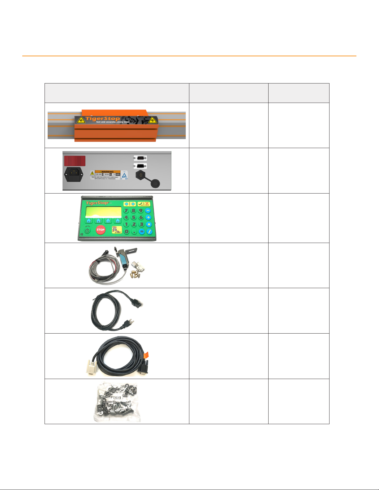
2
Parts Inventory
PART DESCRIPTION
(NUMBER) QUANTITY
TigerStop Beam &
Carriage
(TS-##)
1
Amplifier
(AMP6) 1
TigerStop® Standard
Controller
(CON5)
1
Standard Interconnect
Kit
(SIK)
1
Power Cable
(PC) 1
Data Cable
(CC5-XX) 1
Installation Hardware
Pack
(F0033)
*Includes optional weld nuts
1
Main aSSeMblY

3
Parts Inventory
PART DESCRIPTION
(NUMBER) QUANTITY
Controller Stand Top
(M1803) 1
Square Tube
(M1808) 1
Round Tube
(M1807) 1
Controller Stand
Base Half-Bracket
(M10070)
2
M6x14mm
Socket-Head Screw
(F7216)
1
M6x10mm
Socket-Head Screw
(F7208)
1
M8x50mm
Hex-Head Screw
(F9827)
1
M8x45mm
Hex-Head Screw
(F9826)
2
conTroller STand aSSeMblY

4
Parts Inventory
PART DESCRIPTION
(NUMBER) QUANTITY
Spacer
(F6702) 1
M8x35mm
T-Bolt
(F0184)
2
M8
Flange Nut
(F0419)
5
PART DESCRIPTION
(NUMBER) QUANTITY
Flip-Away Stop
(STOP2) 1
M12 Threaded Rod
(M1405-2) 1
M12 Locking Nut
(F2031) 2
1/2” Nylon Washer
(F1700) 2
flip-awaY STop aSSeMblY
Table of contents
Popular Power Tools Accessories manuals by other brands


ADAMAS
ADAMAS B32 Instructions for use

STEINEL PROFESSIONAL
STEINEL PROFESSIONAL 4007841009595 quick start guide

Echo
Echo Speed-Feed Universal 400 LH/RH Installation and loading instructions

SCHUNK
SCHUNK ROTA TB-TBS-EP Assembly and operating manual

Schmid
Schmid RAPID Secure XL Operation instructions

Drill Master
Drill Master 360X user guide


