Thuli Tables 350 Elevation User manual

Table of Contents
Introduction . . . . . . . . . . . . . . . . . . . . . . . . . 2
Identication of Parts / Motor . . . . . . . . 3 - 4
Table Assembly . . . . . . . . . . . . . . . . . . . . . . 5
Headpiece Attachment & Operation . . . 6 - 10
Table Operation . . . . . . . . . . . . . . . . . . 11 - 12
Accessories . . . . . . . . . . . . . . . . . . . . . . . 13
Care & Maintenance . . . . . . . . . . . . . . 14 -15
Motor Troubleshooting . . . . . . . . . . . . . . . 16
Warranty . . . . . . . . . . . . . . . . . . . . . . . . . . 17
Overview of Products . . . . . . . . . . . . . Back
350 Owner’s Manual
Shown with Metal Base
Crescent Arm Rest
(optional)
THULI TABLES
www.thulitables.com
youtube.com/thulitables
800-458-4854
facebook.com/thulitables
Videos & Manuals

2
Introduction
Rick Thuli, D.C.
President
Sincerely,
We are pleased to provide you with an aesthically beautiful chiropractic
adjusting table that is versatile and precisely engineered. It has been
thoroughly inspected and tested right down to the smallest detail before
leaving our shop. We are condent that it will provide you with many
years of reliable service.
Please take the time to read this manual. It will familiarize you with the
table and instruct you on its proper operation and maintenance.
If you have any questions or comments, please contact us.
Thank you for your purchase of a 350 Elevation table.

Crescent Arm Rest
(optional)
Ankle Rest Extension
Pelvic Section
Fixed Section
Thoracic Section
Ankle Rest
Extension
Locking Knob Pelvic Cocking
Lever & Tension
Control Knob
Thoracic Cocking
Lever & Tension
Control Knob
Identification of Table Parts / Motor Information 3
MOTOR INFORMATION
Electric
Plug
Foot Pedal
Plug
Plug
Clip
Plug
Tab
Screwdriver
If the cord is not attached to
the motor, plug it in, making
sure the clip snaps onto the
tab. A at screwdriver may
be helpful to gently guide the
clip.
To extend the life of the motor, instruct the patient to get on and off at the center of the table.
Avoid elevating or lowering the table while the patient is not centered on the table.
The electric and foot pedal plugs are located at the base of the motor shaft.
Piston

4
Identification of Headpiece Parts
Tension Control Knob
(other side)
Paper Hold-Down Wire
Pivot Block
Slide Block
Paper Hanger
Remote Control Lever
Paper Tear-Off Bar
Straight Drop / Forward
Cocking Lever
Headpiece Mounting Remote Control Cable
Piston Pin
T-Bar
Piston Head
Lowering Lever
Prone Arm Rest Buckle
Flexion / Extension
Prone Arm Rest
Locking Link
Piston
Motion Knob
Bracket
Shown on 300 Stationary

ANKLE REST ATTACHMENT
HEADPIECE ATTACHMENT
ENGAGE T-BAR
1. Place headpiece onto its cushions.
2. Lift the headpiece slide block to a 45 degree angle by grasping
the headpiece lowering lever.
3. Grasp the long rod of the T-Bar and insert it through the hole in
the locking link of the slide block.
4. Lower the slide block to a closed position by applying
counterclock-wise (downward) pressure to the headpiece
lowering lever.
1. Attach the piston/prone arm rest and crescent arm rest
mounting bracket (optional) to the headpiece plate,
matching up the colored dots.
2. Swing the piston/prone arm rest down out of the way
to provide room for attaching the headpiece.
5
Table Assembly
Your table will arrive in two boxes and is easy to assemble. The headpiece and ankle rest extension are packaged
separately from the table. We have included two different wrenches to assist you in the assembly process.
Paper Hold-Down Wire
PISTON / PRONE ARM REST ATTACHMENT
1. Remove the hitch pins and “O” rings from the ankle rest rods.
2. Loosen both ankle rest locking knobs.
3. Slowly insert the ankle rest rods through the frame and plastic
blocks. Note: If the rod does not slide in, the brass spacer that
is inside the plastic block (under the table) needs to be moved
out of the way. Simply insert an allen wrench into the small
hole on the side of the block and push the brass spacer past the
large hole, clearing the way for the rod (photo).
4. Push the ankle rest all the way in and replace the “O” rings
and hitch pins.

HEADPIECE ATTACHMENT (cont)
1. To attach the headpiece to the table, slide it between the
headpiece mounting bracket.
2. Visually line up the hole in the slide block with the top holes
of the mounting bracket and insert the mounting pin with a
twisting motion.
PISTON ATTACHMENT
1. Swing the exion/extension piston down toward the
off-centered slot in the headpiece slide block.
2. Remove the piston pin from the slide block and raise the
front end of the headpiece to allow the piston to engage in the
off-centered slot. If the piston head does not align with the
slot, operate the remote control lever to rotate the head as
needed.
Install the remote control lever into the bottom of the slide block
by inserting the cable into the narrow slot and tilting the cable
end of the lever into the recess until it snaps into place.
Operating the remote control will allow the headpiece to lay
ush with the table cushions.
Attach the Crescent Arm Rest by sliding the slotted end of the
brackets over the mounting rods. Push the front of the Crescent
Arm Rest down so that the plastic bars slide over the foam pads
on the Prone Arm Rest grips.
CRESCENT ARM REST (optional feature)REMOTE CONTROL LEVER ATTACHMENT
6
Table Assembly
3. Attach the piston to the slide block by visually lining up the
holes and inserting the piston pin.
7
Table Operation
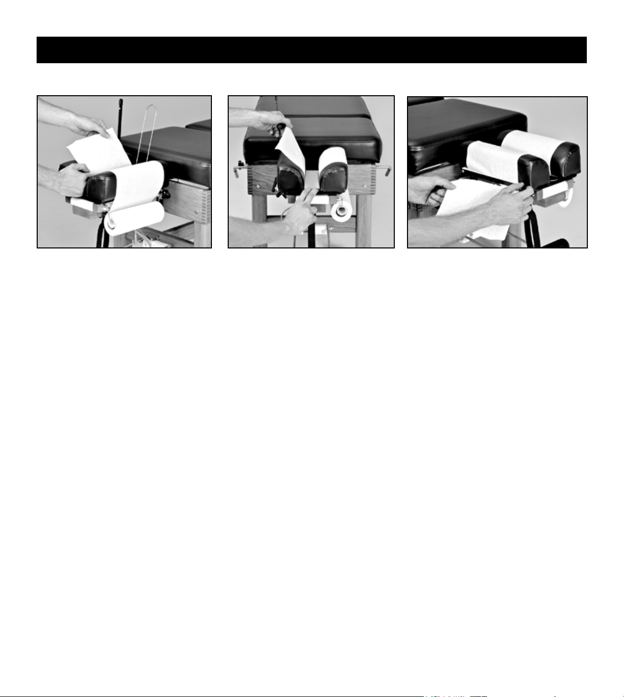
1. Install a 8.5” roll of headpiece paper.
2. Raise the paper hold-down wire and
tear-off bar. Advance the paper and
tuck it between the cushions.
3. Lower the hold-down wire between
the cushions, lower the tear-off bar
and tear off any excess paper.
HEADPIECE PAPER
4. To advance the headpiece paper, raise
the tear-off bar, hold your nger on
the hold-down wire and pull the paper
across the cushions. Pulling the paper
in an upward direction will reduce
friction, making it easier to pull.
5. To tear off used headpiece paper, use an
upward motion while holding down the
tear-off bar.

8
Headpiece Operation
STRAIGHT DROP FORWARD MOTION DROP
Flex and extend the headpiece by
grasping the front end of the headpiece
and operating the exion/extension
control lever.
LATERAL FLEXION (optional)
To ex the headpiece laterally, turn the
lateral exion lever in a counterclockwise
direction, manually position the headpiece,
then lock it into position by tightening
the lateral exion lever. This can be done
while the headpiece is in the exed,
extended or elevated position.
LATERAL FLEXION LEVER
The position of the lateral exion lever
can be changed. With the lateral exion
lever tightened, pull the lever directly
outward, rotate to the desired position
and release.
Knob pulled out
PRIOR to cocking
Knob pushed in PRIOR to cocking
FLEXION / EXTENSION
PRIOR to cocking the headpiece, set for straight drop by
pulling out the headpiece straight drop/forward motion knob
until you feel it is “set” into position. This will be just short
of coming into contact with the cocking bar. If you pull the
knob out too far, simply push it back in and continue.
PRIOR to cocking the headpiece, set for forward motion drop by
pushing in the headpiece straight drop/forward motion knob.
Cock the headpiece with an upward motion on the headpiece cocking lever.
Please note: Be sure to change the headpiece drop function
before cocking the headpiece to prevent an ineffective drop and
damage to the drop mechanism.
Set the desired tension by turning the tension control knob clockwise (increasing tension) or counter-clockwise (decreasing tension).

9
VERTICAL ELEVATION
Headpiece Operation
2. Raise the front end of the headpiece
by operating the exion/extension
control lever.
3. With practice, steps 1 and 2 can be
combined to vertically raise the
headpiece in one smooth motion.
VERTICAL LOWERING
1. Lower the front end of the headpiece
by operating the exion/extension
control lever.
2. In one smooth motion, lower the back
end of the headpiece by lifting the
headpiece lowering lever with one
hand while gently lowering the back
end of the headpiece with the other.
1. Raise the back end of the headpiece
by lifting the grey grip of the cocking
lever (without operating the lever).
Caution: Do not grasp the cushions to
raise the back end, which could stretch
and damage the small springs.

10
Headpiece Operation
PRONE POSITION
EYE COMFORT IN PRONE POSITION
For patients who are sensitive to pressure on their eyes, slightly raise the back end of the
headpiece. This will take pressure off of the eyes by supporting the weight of the head
at the mandible and zygomatic arches. Using this maneuver, in combination with slight
exing of the headpiece, will provide additional comfort for many patients.
Side posture positioning of the patient’s
head for lumbo-pelvic adjusting or
toggle recoil adjusting.
SIDE POSTURE POSITION SUPINE POSITION
Position the headpiece vertically to give
maximum support of the cervical spine and
patient’s head when in a supine position.
Position the patient sufciently forward
with arms outstretched and wrists resting
comfortably on the Prone Arm Rest, which
is adjustable in height. To raise, pull on
the loop at the end of the strap. To lower,
squeeze the cam lock (to loosen the strap)
and pull down on the Prone Arm Rest
grips. Advise the patient not to apply
weight on the Prone Arm Rest while
getting up from the table.
HEADPIECE CUSHIONS: ADJUSTABLE WIDTH
Neutral position. Narrower position for smaller faces
(eg children).
Wider position takes pressure off of
the patient's eyes.
The headpiece cushions are easily adjustable in width at the front end for individualized patient comfort. Firmly pull up on the front
end of each headpiece cushion and move in (one or two notches) or out (one or two notches) to desired position. Secure cushions
by engaging locating pins into notches provided.
This manual suits for next models
9
Table of contents
Other Thuli Tables Medical Equipment manuals


