Thiele Streamfeeder Tagger 125 Series User manual

Manual
Series 125 Tagger

© 2016 Thiele Technologies, Inc. - Streamfeeder. All rights reserved.
No part of this publication may be reproduced, photocopied, stored on
a retrieval system, or transmitted without the express written consent of
Thiele Technologies, Inc. - Streamfeeder.
Thiele Technologies, Inc. - Streamfeeder
315 27th Avenue NE
Minneapolis, MN 55418 USA
Tel:(763) 502-0000
Fax:(763) 502-0100
e-Mail: service@streamfeeder.com
Web: www.streamfeeder.com
Printed in the USA.
1Tag Feeder Manual
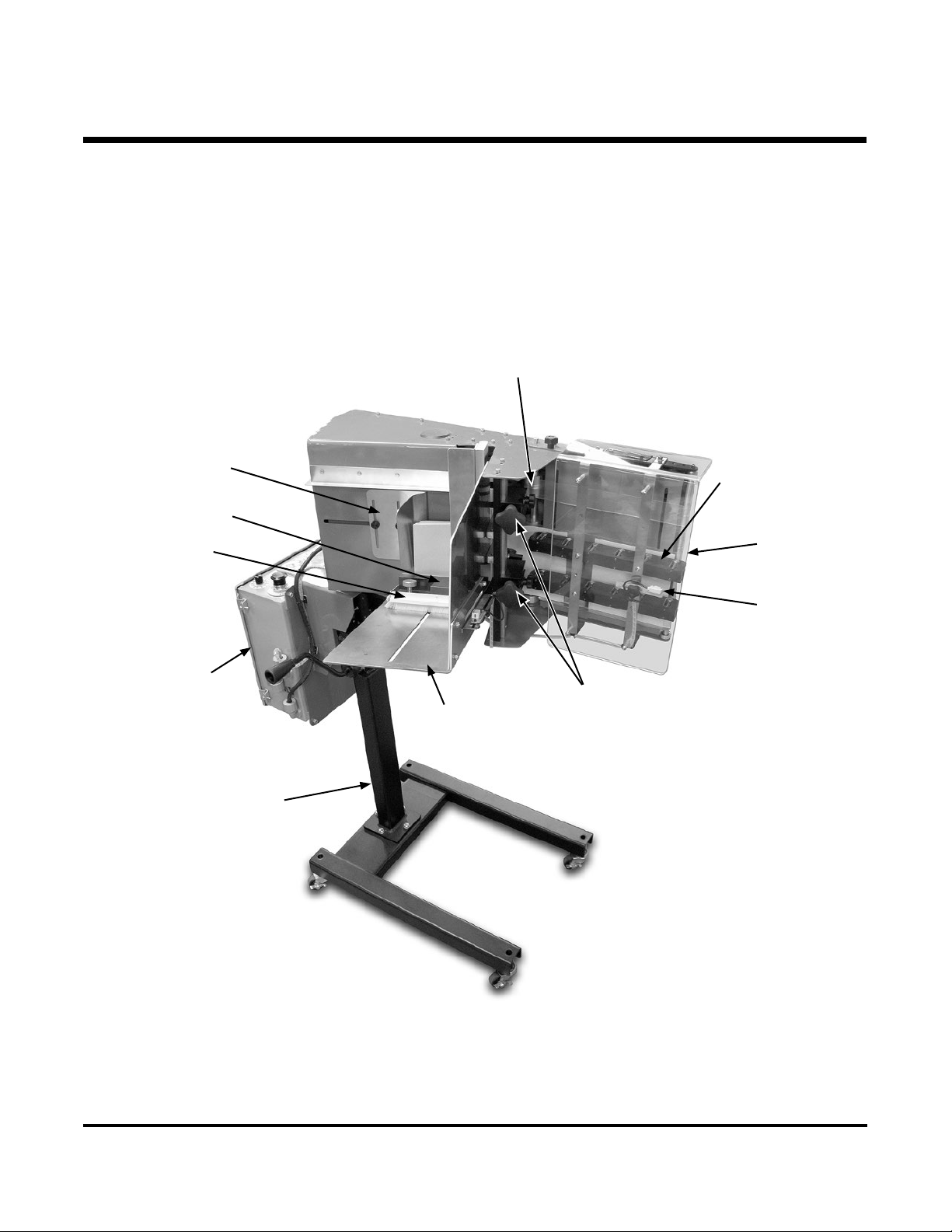
Review the main assemblies below to become familiar with names
and locations of feeder parts and adjustments. This will help to prepare
you for initial setup.
1About the Machine
Main Assemblies
Feed
Belts
Wedge
Assembly
Roller Wedge
Assembly
Pressure Plate
Product
Hold Down
Product
Tray
Discharge
Assembly
Product
Staging
Sensor
Controller
Mounting
Stand
Gate
Assemblies

2
Tag Feeder Manual
Feature Description
Main Assemblies Feature Descriptions
Feed Belts Provide the friction necessary to drive the tags through the separator and into the discharge.
Wedge Assembly Provides a light lift of the rear of the tag stack when loaded. This is critical to ensure that the
tags ow smoothly around the separators.
Product Tray Where the stack of tags are loaded.
Product Hold Down Applies pressure to the stack of tags as they ow through the product tray to ensure separation
of the tags are consistent.
Gate Assemblies Provide a gap between them and the feed belts to allow one tag to feed out at a time while
retaining the rest of the stack.
Discharge Assembly Receives the tags one at a time, accelerates it to create a gap, and positions the tag at the tag
detect sensor mounted at the end of the discharge. The discharge has spring loaded wheel
assemblies that require no adjustment and is covered by a guard to keep excessive dust out.
Controller Provides the logic and controls to operate the machine.
Product Staging Sensor Detects the leading edge of each piece to "stop" each cycle.
Pressure Plate Provides consistent stack pressure of the product onto the feed belts.
Mounting Stand The stand supports the feeder.
3Tag Feeder Manual
2Preparing for Operation
Below you will see the two main types of sewing machine congurations
for which we offer a Single Stage or a Dual Stage conguration.
Installation Use the single-stage discharge for infeeds like this
Use the dual-stage discharge for infeeds like this
Direction of
bag travel
Direction of
bag travel
Single stage
tagger feed
position
Dual stage tagger
feed position

4
Tag Feeder Manual
Depending on available locations, the trigger sensor and reector should
be mounted in an area along the conveyor that will allow it to detect
the bags as they come into the sewing machine. It is important that the
location is not interfered with by operators which could result in miss-
feeds. The provided mounting hardware will allow you to mount the
sensor and reector directly on the sewing machine frame.
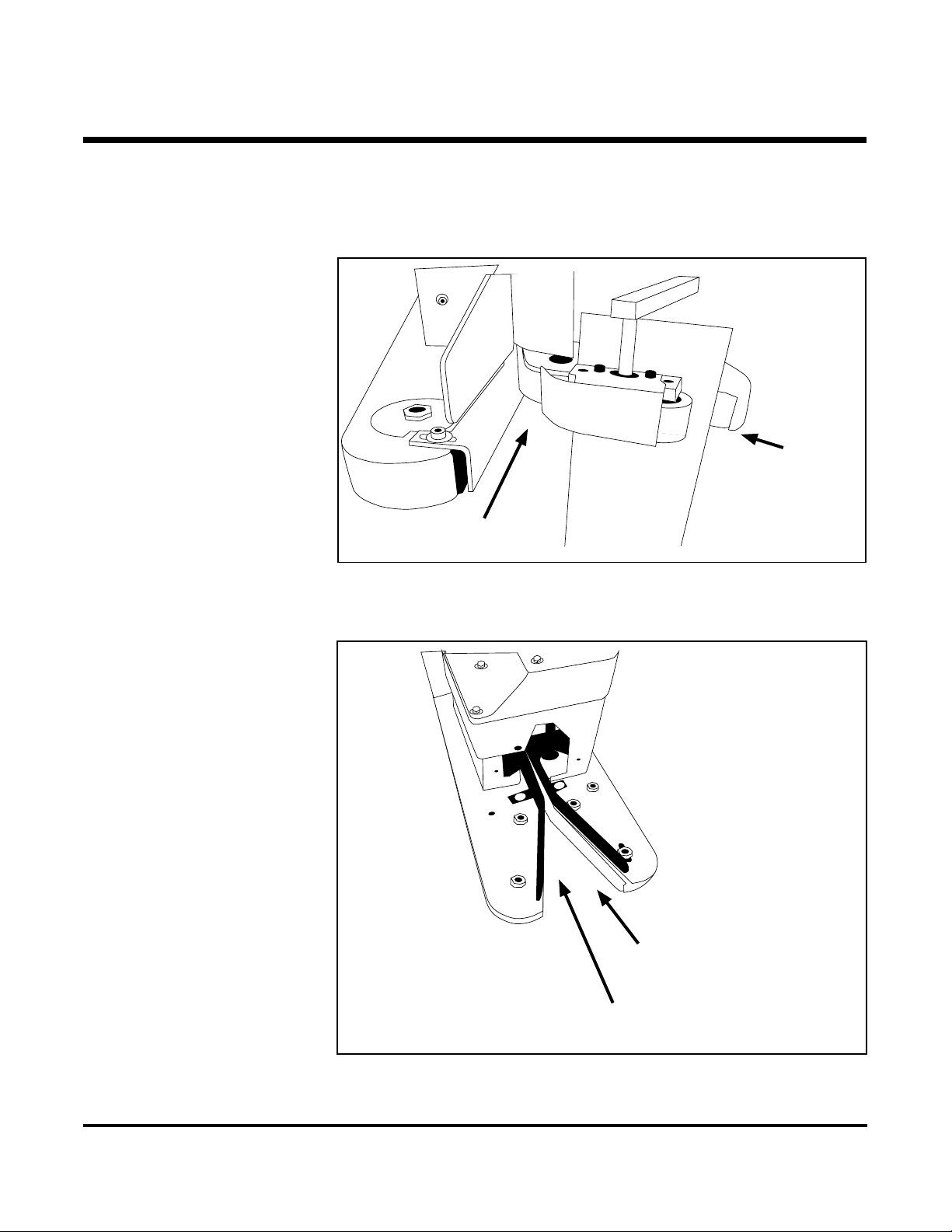
Slide and set the pressure plate at the full rear/up position. Secure in
place with the detent knob.
Raise the gates a couple turns off the belt by turning the knob clockwise.
Insert a single tag between the separators and feed belts. Begin turning
one of the separator knobs counter clockwise while you slide the tag
back and forth until a slight drag is made. Then repeat with the second
separator. Once both are equally set, turn both knobs additionally
counter clockwise ¼ turn.
With a tag in position at the separators, add another 1-2” of tags to the
stack. Move the wedge in just so it makes contact with the rear of the
tags.
Continue loading product in the product tray. When loaded, release the
detent knob and allow the pressure plate to make contact with the stack.
Make sure the detent knob is in the full up position so that the pressure
plate slides freely.
Plug the machine into a properly grounded 120V outlet and release the
Estop button.
Mounting
Trigger Sensor
Set the Gates
Set the Wedge
Load Product
Turn on Power

5Tag Feeder Manual
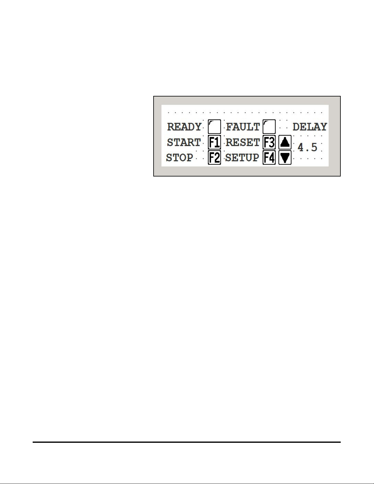
HMI Displays User Interface
Upon power up the machine will default to Screen 1: RUN SCREEN
Press F4 to advance to screen 2:SETUP SCREEN
3Operation

6
Tag Feeder Manual
HMI Displays
Press the F1 key to jog the feed motor. – This will incrementally advance
tags from the stack and into the discharge and eventually out of the dis-
charge. While jogging, ensure that only one tag is coming out at a time and
that there is at least 1” spacing between each tag.
If tags are coming out in doubles, lower the separators CCW another ¼ turn.
Press the up arrow key to increase the delay time for the start of the tag feed
after the trigger sensor is made. – This value will vary based on the speed of
the system. When running slow, the value will be higher than when running
fast.
With Miss FLT on, the machine will go into an error state when multiple
triggers have come into the machine before the rst cycle was completed.
Press F2 to turn on or off.
Press ESC to return to RUN SCREEN.
7Tag Feeder Manual
HMI Displays Ready Indicator: The indicator turns black when the tagger is ready to ac-
cept trigger signals.
The fault indicator turns black on any error that stops the tagger from ac-
cepting trigger signals.
Press the F1 key to stage/start the tagger.
Press the F2 key to put the tagger in a paused state.
Press the F3 key to reset a faulted condition.
Test cycle Manual. For further setup testing, press and release the F1 key to
cycle the machine. One tag should be dispensed and the next one staged to
the tag detect sensor. Repeat as necessary.
Test cycle Automatic. To automatically test the machine, it will need to be
put into ready mode rst. Press F3 and then F1. The indicator next to the
word READY should change to black.
Run a bag through the conveyor and into the sewing machine. The bag
should trip the sensor and turn on the feeder to dispense a tag into the sew-
ing machine which will bring the tag onto the bag.
To set the position of the tag on the bag, use the up / down arrows to either
increase or decrease the trigger delay.
Repeat until tag is in desired position. Please note that relocation of the
trigger sensor and reector may be needed if you run out of adjustment
either way.

8
Tag Feeder Manual
For proper operation of the machine, periodic maintenance is required and
only takes a few minutes to complete.
Clean the feed belts and discharge belts as needed, no more than weekly
using a rag and isopropyl alcohol. Isopropyl alcohol is the best solution for
refreshing the belts and cleaning the dust off them. It can be purchased at
any Walgreens / CVS type stores.
As you are cleaning the belts, visually check the condition of the timing
belts to look for fraying or cracking – replace as needed.
Gate o-rings will need to be rotated as they develop at spots on them. The
best way to determine if they need to be rotated is that the machine will start
feeding doubles.
To adjust, simply loosen the screw and rotate the o-ring spool 1/8”.
Finally, a clean machine is a happy machine. Make sure to blow off dust
and contaminants on a regular basis.
4Maintenance


