Thermo Scientific Vanquish Charger User manual

thermoscientific
Vanquish
Solvent Monitor
Installation Guide
4822.3010-EN Revision 1.0 •January 2020

Copyright © 2020 Thermo Fisher Scientific Inc. All rights reserved.
Trademarks
All trademarks are property of Thermo Fisher Scientific and its subsidiaries.
Disclaimer
Thermo Fisher Scientific Inc. provides this document to its customers with a product purchase to
use in the product operation. The document is copyright protected; any reproduction of the
whole or any part of this document is strictly prohibited, except with the written authorization
of Thermo Fisher Scientific Inc.
This manual is provided "as is." The contents of this manual are subject to being changed,
without notice, in future revisions.
Thermo Fisher Scientific Inc. makes no representations that this document is complete,
accurate, or error-free. Thermo Fisher Scientific Inc. assumes no responsibility and will not be
liable for any errors, omissions, damage, or loss that might result from any use of this document,
even if the information in the document is followed properly.
This document is not part of any sales contract between Thermo Fisher Scientific Inc. and a
purchaser. This document shall in no way govern or modify any Terms and Conditions of Sale.
The Terms and Conditions of Sale shall govern all conflicting information between the two
documents.
Printed manual version only
Printed in Germany on 100% chlorine-free bleached, high-white paper that is produced in an
environmentally friendly process, leading to a paper profile of zero CO2 emissions.

Contents
Solvent Monitor
Installation Guide
Page 3
Contents
1 About this Manual ....................................................................... 5
2 Overview ..................................................................................... 6
3 Installation................................................................................... 7
3.1 Scope of Delivery....................................................................................................7
3.2 Rating Plate ............................................................................................................7
3.3 Allowed Concentrations .........................................................................................7
3.4 Installing the Solvent Monitor................................................................................8
3.5 Connecting Signal Cables to the Solvent Monitor ................................................10
3.6 Connecting the Solvent Monitor Lines .................................................................14
3.6.1 Short Solvent Monitor Lines..................................................................... 14
3.6.2 Long Solvent Monitor Line ....................................................................... 19
4 Operation................................................................................... 24
4.1 Status Indicators...................................................................................................24
4.2 Operating Principle...............................................................................................26
4.3 Notes on the Solvent Monitor Operation.............................................................26
5 Maintenance and Service ........................................................... 29
5.1 General Rules for Maintenance and Service ........................................................29
5.2 Routine and Preventive Maintenance..................................................................30
5.2.1 Maintenance Plan .................................................................................... 30
5.3 Replacing the Solvent Monitor Lines....................................................................30
5.4 Replacing the End Caps ........................................................................................32
5.5 Replacing the Retaining Guides............................................................................33
5.6 Updating the Device Firmware.............................................................................34
6 Troubleshooting......................................................................... 35
6.1 General Information about Troubleshooting .......................................................35
6.2 Operating Issues ...................................................................................................35
6.3 Messages ..............................................................................................................38

Contents
Page 4 Solvent Monitor
Installation Guide
7 Specifications ............................................................................. 42
7.1 Performance Specifications..................................................................................42
7.2 Physical Specifications..........................................................................................43
8 Ship Kit....................................................................................... 44
9 Consumables and Replacement Parts......................................... 46

1 • About this Manual
Solvent Monitor
Installation Guide
Page 5
1 About this Manual
This manual provides instructions for installation, set up, maintenance
and troubleshooting.
This manual is intended as a supplementary document to the Operating
Manual for your pump. Refer to the Operating Manual for general safety
information and the typographic conventions used throughout this
manual.
Illustrations in this manual are provided for basic understanding. They
can vary from the actual model of the device or component. However,
this does not influence the descriptions. No claims can be derived from
the illustrations in this manual.

2 • Overview
Page 6 Solvent Monitor
Installation Guide
2 Overview
The Vanquish Solvent Monitor (VSM) tracks the volume in solvent
reservoirs and waste containers based on physical measurements. It
enables routine customers to run their HPLC systems safely and with
minimum downtime.
The solvent monitor can be controlled and the volumes can be visualized
via the:
•ePanel in the Chromeleon™ software
•Chromeleon parameters
If a Vanquish System Controller is also installed, the measured volumes
can also be monitored via the Vanquish Display or an internet web
browser.

3 • Installation
Solvent Monitor
Installation Guide
Page 7
3 Installation
3.1 Scope of Delivery
The following items are included in the delivery:
•Solvent monitor
•Ship Kit
•Installation Guide
For information on contents of the ship kit or reordering parts, see Ship
Kit (}page44) and Consumables and Replacement Parts (}page46).
3.2 Rating Plate
The rating plate is located on the rear side of the solvent monitor. The
rating plate indicates the serial number, part number, module name,
revision number (if any), line rating, and the manufacturer's address.
3.3 Allowed Concentrations
The allowed salt concentration for the solvent monitor is 1 mol/L or less.
NOTICE
If the solvent monitor is used in a Vanquish Core system, observe the
lower chloride concentration allowed for this system (refer to the
Vanquish System Operating Manual).

3 • Installation
Page 8 Solvent Monitor
Installation Guide
3.4 Installing the Solvent Monitor
TIP If the system stack has not already been set up, install the solvent
monitor before the column compartment because the cables need to be
guided between the system stack and the column compartment.
The recommended position of the solvent monitor is the right side of
the front railing.
Figure1: Recommended position of the solvent monitor
If a Vanquish Display is also to be installed, refer to the Vanquish User
Interface Installation Guide for information where to mount the
Vanquish Display. The instructions below describe how to mount the
solvent monitor at the right side of the front railing.

3 • Installation
Solvent Monitor
Installation Guide
Page 9
If personnel other than a Thermo Fisher Scientific service engineer
installs the device, follow the steps below.
1. Loosen the screw of the mounting bracket on the rear side of the
solvent monitor.
2. Hook the mounting bracket of the solvent monitor onto the right
side of solvent rack railing.
Figure2: Hooking the solvent monitor onto the right side of the solvent
rack railing (view from the right side)
3. Fix the mounting bracket to the railing by fastening the screw.
Figure3: Fastening the screw
3 • Installation
Page 10 Solvent Monitor
Installation Guide
3.5 Connecting Signal Cables to the Solvent Monitor
Device Connectors
The following connectors are provided on the device:
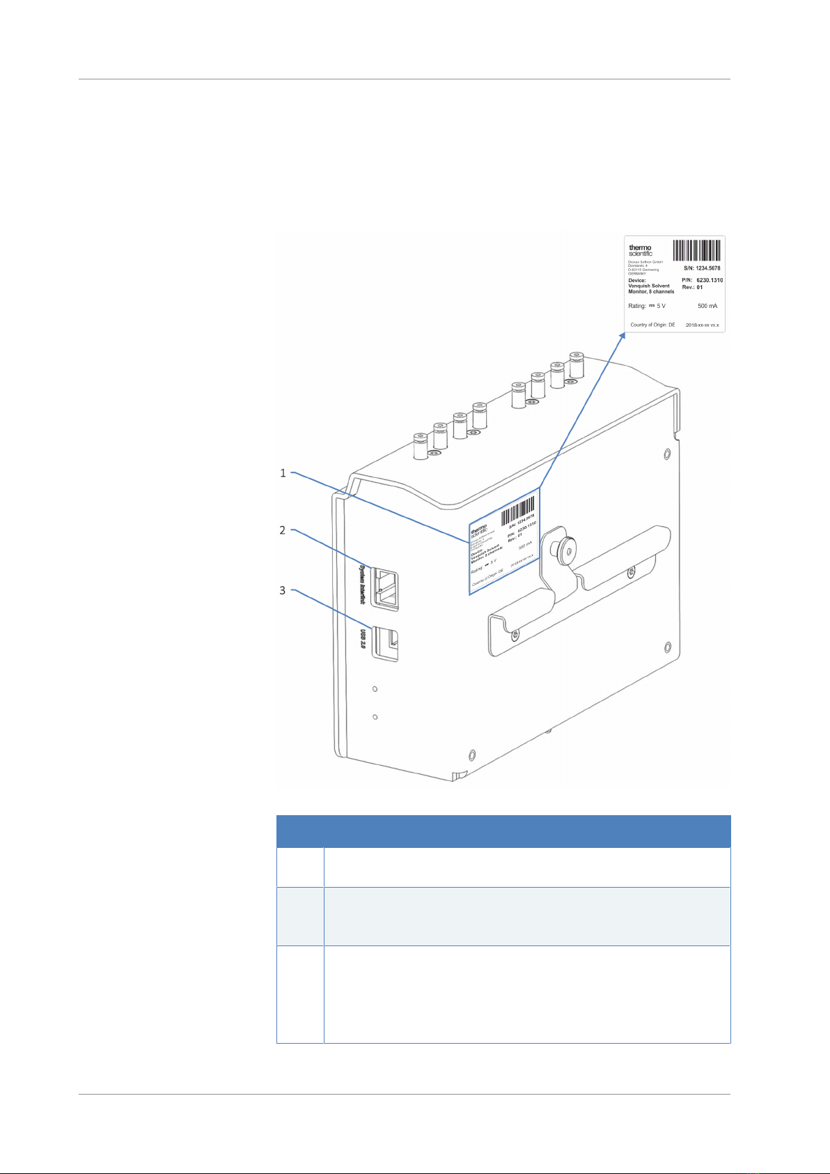
Figure4: Connectors on the rear side of the solvent monitor
No. Description
1 Rating plate, indicating the serial number, part number, module name,
revision number (if any), and the manufacturer's address
2 System Interlink port
Allows device communication and synchronization between the device and
other modules in the Vanquish system.
3 USB (Universal Serial Bus) port ("B" type connector)
Allows:
•Connection to the computer on which the data management system is
installed
•Power on/off control for the solvent monitor
Other manuals for Vanquish Charger
2
Table of contents
Other Thermo Scientific Monitor manuals

Thermo Scientific
Thermo Scientific Alpha pH 550 User manual

Thermo Scientific
Thermo Scientific ALPHA COND 550 - REV 5 User manual

Thermo Scientific
Thermo Scientific ALPHA COND 550 User manual

Thermo Scientific
Thermo Scientific 5028i User manual

Thermo Scientific
Thermo Scientific Orion 2111LL User manual

Thermo Scientific
Thermo Scientific personalDATARAM pDR-1000AN User manual

Thermo Scientific
Thermo Scientific SAM12 User manual

Thermo Scientific
Thermo Scientific Alpha pH 550 User manual

Thermo Scientific
Thermo Scientific INNOVA Series User manual

Thermo Scientific
Thermo Scientific 3600 PDM User manual


