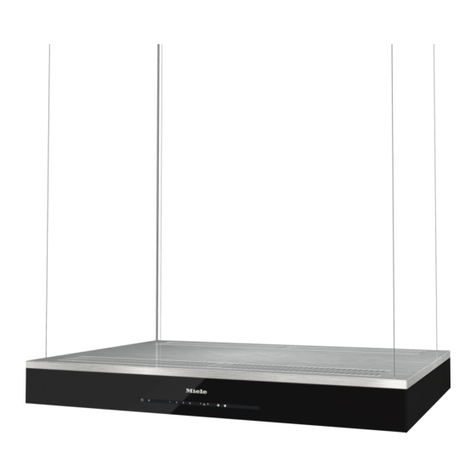
HOOD DESCRIPTION
1) Motor speed button
2) Light button
3) Operating light
4) Exhaust grate
5) Work-light
USE
The hood may be used as follows:
— Exhaust version for venting outdoors
— Filter version with internal recycling
Exhaust version for venting
outdoors
The air is vented outdoors by a duct which
must be connected to connecting ring A
(Fig. 1).
For 90cm. hood
Check if the internal shutter Pare opened
before using the hood (Fig. 10).
Filterversionwithinternalrecycling
Theairisfilteredthrough acarbonfilter and
recirculated into the room through the grat-
ing. This version is used when there is no
exhaust duct for venting outdoors or when
it is impossible to install one. To use the
hood in this version, proceed as follows:
— If no filter is supplied with the hood, ask
the technical assistance service or the
manufacturing company for one and
specify the hood model.
— To install the filter, fit it in the seat at the
frontandfastenitatthebackwiththetwo
hooks B(Fig. 2).
For 90cm. hood
Attention! Close the shutter Pbefore using
this version of the hood (Fig. 10)
INSTALLATION
When installed, the hood must be not less
than 65 cm. above electric burners or 75
cm. above gas or mixed-fuel burners. (h,
Fig. 3).
In the vented exhaust version the fumes
outletductmustbe120mm. in diameter. In
thehorizontal runstheductmust beslightly
slanted(about10°)anddirectedupwardsto
vent the air easily from the room to the
outside.
Electric hook-up
Before completing any connection, make
sure the house voltage corresponds with
the voltage indicated on the label affixed
inside the hood.
The hood may be supplied with a standard
plug and if so connect it to a correspond-
ingly standard socket.
If the appliance is not fitted with a plug, fit a
plugconformingtoregulationswithanopen-
ing distance between contacts of not less
than 3 mm.
The manufacturers are not liable for any
problems caused by the user’s failure to
observe the above instructions.
Fastening the hood to the wall
(Fig. 4)
—Positionthetemplateinthecorrectposi-
tion and make two 8mm diameter holes
and two 12mm diameter holes.
—Fitthetwo8mmdiameterplugsinthetop
holes.
— Fasten the two hooks Cin the bottom
holes.
— Hang the hood on the hooks and level it
with the screws D.
— Secure it in place with the two 5x45 mm
screws and 5-20 mm diameter washers
in the top holes.
The screws and washers are standard
equipment.
Installingthe ductforventingto out-
side (exhaust version)
(Fig. 5-6)
—FastenthetopsupportEtothewallclose
to the ceiling on the perpendicular of the
bottom connections. To do use the two
8mm diameter screws and plugs sup-
plied as standard equipment.
— Take the measure between the ceiling
and the hood top, and adjust the duct to
this height. Fasten it with the screws F
(Fig. 6).
— Insert the duct with the slots downwards
andfastenit with the twotopscrewsand
the two bottom screws G.
Installing the duct for recycling into
the room (filter version)
Perform the same operations described
in the preceding paragraph. With screws
supplied,fastentheairconveyorMinside
the duct (Fig. 9).
FASTENING OF SHELVES (optional)
(Fig. 7)
Fasten the four side supports Ito the adja-
cent cabinets and place the shelf on the
supports.
OPERATION
— The hood is provided with a motor with
several speeds. For the best perform-
ance, we recommend using the low
speeds in normal conditions and the
highspeeds inparticularcases ofstrong
odour and vapour concentration.
— We recommend starting up the hood a
fewminutesbeforecookingandkeeping
it running until all the odours have been
eliminated.
— To start the appliance, pull the control
panel downwards for access to the light
and motor switches.
Thehoodhasamicroswitchsothatonce
the motor speed has been selected and
the light switched on, the hood can be
started by simply pulling out the control
panel.
When the panel is closed, the hood
switches off.
The control panel can be positioned at
the desired angle to light the cooking
area.
ATTENTION
If the hood is run at the same time as a
burner or fireplace that depend on ambient
air (for example gas, Diesel, coal or wood
heaters, water heaters, etc.) be careful,
becausethehood,whenitexhausts theair,
removes the ambient air required by the
burner or fireplace for combustion.
For secure operation and to prevent dis-
charged gas from coming back in, the
vacuum must not exceed 0,04 mbr.
This may be done by making sure the air
inlet into the room passes through non-
closing openings such as air recycling wall
boxes,doors,windowsorwithothertechni-
cal measures.
Please, keep to the provisions of official
directives regarding the question of fume
discharge.
No food must be cooked flambe under-
neath the hood.
Theuseofanunprotectedflameisdanger-
ous for the filters and could cause fires.
Therefore, never use an open flame under
the hood. When frying foods, never leave
thepanalonebecausethecookingoilcould
flare up.
The hood must not be connected to fuel
exhaust flues (boilers, heating systems,
water heaters, etc.).
The manufacturers refuse to accept any
responsibility for damage to the hood or its
catching on fire because of failure to ob-
serve the above instructions.
MAINTENANCE
Beforeperforminganymaintenanceopera-
tion, disconnect the hood from the electric-
ity.
Grease filter
Thisservestoholdthegrease particlesin
suspension.
To remove the filter, push it towards the
back of the hood and pull it downwards
(Fig. 8). To clean, wash it in hot water and
biodegradable detergent. Let dry before
reinstalling. Clean it at least once a month.
10 11
GB