Terasic de10-nano User manual

DE10-Nano
D8M RTL
1 www.terasic.com
February 24, 2017
1
1.
.
I
In
nt
tr
ro
od
du
uc
ct
ti
io
on
n
This document illustrates how to setup the Camera demo on the DE10-Nano and the
D8M-GPIO as shown in shown in Figure 1. The basic design content is also included.
In this demonstration, please refer to the DE10-Nano user manual. For details about
the D8M-GPIO, please refer to the user manual of D8M-GPIO daughter card.
Figure 1 Camera Demo
2
2.
.
S
Sy
ys
st
te
em
m
R
Re
eq
qu
ui
ir
re
em
me
en
nt
ts
s
The following items are required to perform this demonstration:
DE10-Nano and power supply
D8M-GPIO
HDMI-Monitor
3
3.
.
E
Ex
xe
ec
cu
ut
te
e
D
De
em
mo
on
ns
st
tr
ra
at
ti
io
on
n
Please follow the procedures below to setup the demonstration
1. Make sure both Quartus II and USB-Blaster II driver are installed on the host
PC.
2. Make sure Quartus Prime 16.0 Standard or later is installed on your host PC.
3. Power off the DE10-Nano board
4. Make sure the MSEL[4:0] is set to 10010.
5. Mount the D8M-GPIO onto the 2x20 GPIO_0 expansion header of the DE10-
Nano.
6. Power on the DE10-Nano Board.
7. Execute the demo batch file “test.bat” from the directory
\FPGA\DE10_NANO_D8M_RTL\demo_batch
8. Now, you should see the HDMI monitor

DE10-Nano
D8M RTL
2 www.terasic.com
February 24, 2017
9. LED0~1 light up, stand the settings of D8M-GPIO MIPI decoder IC and
Camera Sensor I2C are completed..
10. LED2 when plug HDMI monitor cable generates an interrupt signal. LED2
will extinguish, and after bright.
11. LED3 blink in 1Hz, stand MIPI_PIXEL_CLK are generated correctly.
12. D8M-GPIO capturing image displays on HDMI monitor, if the HDMI monitor
image is fuzzy, please press KEY1 one time again (will perform the focus
operation again). Users can switch SW3 to “1” (there will be a yellow box on
image), then, press SW3 one time again, the middle area focus operation will
be performed.
13. Table 1 summarizes the functional keys and details of each LED status.
Table 1 The functional keys of the digital camera demonstration
Name Description
LED0 Lights up when MIPI DECODER I2C setting is successful
LED1 Lights up when CAMERA I2C setting is successful
LED2 When HDMI cable plug , LED Blink (blanking)
LED3 Blink in 1HZ (D8M-GPIO PIXE CLOCK /25M)
KEY0
SYSTEM RESET
KEY1
Image auto focus(area based on SW3 selection)
SW3
0: No yellow box (focus on whole screen area)
1: There is a yellow box(focus on yellow box)
SW0
0: 1KHz Sound OFF
1: 1KHz Sound ON
4
4.
.
P
Pr
ro
oj
je
ec
ct
t
D
De
es
sc
cr
ri
ip
pt
ti
io
on
n
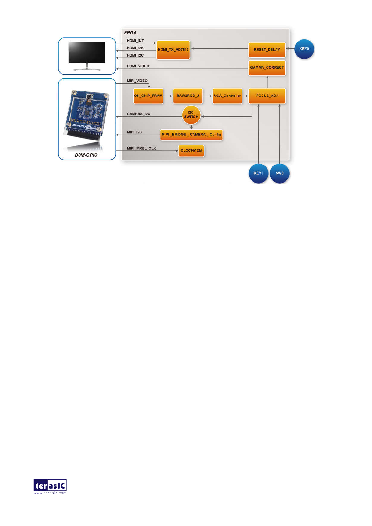
Figure 2 shows the System block diagram of Camera demonstration. This design
block is one dual-port-ram Control module can control on chip Memory and
read/write image data. Camera raw data will be written in on-chip-ram first. After
finishing writing a Frame, ON-CHIP_FRAM module will read out the data from dual-
port-ram to RAW2RGB_J module to convert RAW data to RGB data. The RGB data
will output along with the signal timing generated by VGA_Controller to LCD . In the
block, other module (for example, FOCUS_ADJ, MIPI_BRIDGE_CAMERA_Config )
function instructions and KEY/SW operation. All module functions are described
below:

DE10-Nano
D8M RTL
3 www.terasic.com
February 24, 2017
Figure 2 System Block Diagram
RESET_DELAY: When press KEY0 , this module will provide LOW signal of
about 0.25 seconds for the whole system module to do RESET.
ON_CHIP_FRAM:This module is one dual-port-ram controller can control 640
x 480 x10bit on-chip ram and read/write image data
MIPI_BRIDGE_CAMERA_Config:the MIPI BRIDGE I2C and Camera I2C
setting controller, such as set to output 480P@60Hz timing. It mainly writes I2C
corresponding parameters to MIPI-BRIDGE IC register and Camera Sensor IC
register respectively through their own I2C buses. MIPI_I2C bus is used to write
MIPI BRIDGE I2C (I2C Slave Address = 0x1c.), CAMERA_I2C bus is used to
write Camera Sensor (IC Slave Address = 0x6c).
RAW2RGB_J: This module is to convert RAW data to RGB data.
VGA_Controlle : the LCD signal timing generator, can generate 480P@60 Hz
signal timing.
FOCUS_ADJ: This module provides two main functions.
The first function is using I2C bus to write D8M Voice Coil Motor (VCM) driver
IC register, and control the camera lens’ movements to perform image focusing.
VCM driver IC register (I2C Slave Address =0x18) shares I2C bus with camera
module. The other function is doing the current image high frequency component
statistic. When the VCM drives the camera lens’ movement, a real-time statistics
of image high-frequency sum will be done in every step of the moving. Finally,
the lens will move to a position which has the largest number of high frequency
to complete the automatic focus operation. Focus area can be selected by SW3.
There are two options:
Select focusing the whole screen area (set SW3 to 0)
Select focusing the middle area (set SW3 to 1).

DE10-Nano
D8M RTL
4 www.terasic.com
February 24, 2017
Once you set SW3 to a value (0 or 1) and press KEY1 one time, the automatic
focus operation will be performed in the selected area.
GAMMA_CORRECT: by Bézier Curve in real time (none LUT-TABLE)
produce GAMMA curve generate new RGB's data
HDMI_TX_AD7513: This module will setting AD7513 (HDMI TX ) I2C setting
controller, set register respectively through own I2C buses. (I2C Slave Address =
0x72), and 1KHz sine wave by I2S bus send to AD7513 output sound.
CLOCKMEM: This module will divide MIPI_PIXEL_CLK (25MHz) to 1Hz to
display on LEDs
Other manuals for de10-nano
4
This manual suits for next models
1
Table of contents
Other Terasic Digital Camera manuals