Telwin Superior240 CE Operating instructions

inverter
“reparation no-problem”
Cod.988367
CONTENTS PAG E
OPERATION AND ELECTRICAL DIAGRAMS................... 2
- Block diagram 2
- Analysis of block diagram 3
- Illustrations 5
- Electrical diagrams 7
REPAIR GUIDE.................................................................. 11
- Equipment required 11
- General repair instructions 12
- Troubleshooting and remedies 12
- Testing the machine 15
- Illustrations 17
SPARE PARTS LIST.......................................................... 21
REPAIR SHEET................................................................. 23
TROUBLESHOOTING
AND REPAIR MANUAL
TROUBLESHOOTING
AND REPAIR MANUAL
TROUBLESHOOTING
AND REPAIR MANUAL
TROUBLESHOOTING
AND REPAIR MANUAL
30/06/02
SUPERIOR 240 CE

2
BLOCK DIAGRAM
OPERATION AND WIRING DIAGRAMSOPERATION AND WIRING DIAGRAMS
SUPERIOR 240 CE
1927
14 26
1 2 3 4 5 6 7 8 9 10 11
FAN MAX. CURRENT
LIMITER
+
-
25
SHUNT
AMPLIFIER
15 1617
18
32
MMA
TIG-LIFT
HOT START
ARC FORCE
20 21 36 35 12 13
24
22 23 34
29
30
31
33
27
28
+
-
MAINS INPUT EMC FILTER VARISTOR PRE-CHARGE RECTIFIER FILTER CHOPPER PR.CURRENT TRANSFORMER SEC. DIODES NDUCTANCE SEC.EMC OUTPUT
BRIDGE CONTROL SHUNT FILTER
UNDERVOLTAGE
SAFEGUARD
OVERVOLTAGE
SAFEGUARD
POWER SUPPLY
LED
FLYBACK POWER DRIVER CURRENT READER
SUPPLY AND LIMITER PR.
PHASE FAILURE
FUNCTION
SELECTOR
AUXILIARY
POWER SUPPLY
SHORT CIRCUIT
DETECTOR
ALARM BLOCK ADDER
DUTY CYCLE
MAKER
DIODE
THERMOSTAT SEC.
POWER
TRANSFORMER
THERMOSTAT
ALARM LED CURRENT
POTENTIOMETER
SHORT
CIRCUIT DELAY
HOT-START
ARC-FORCE
POTENTIOMETER
DUTY CYCLE
LIMITER

SUPERIOR 240 CE
Block 9
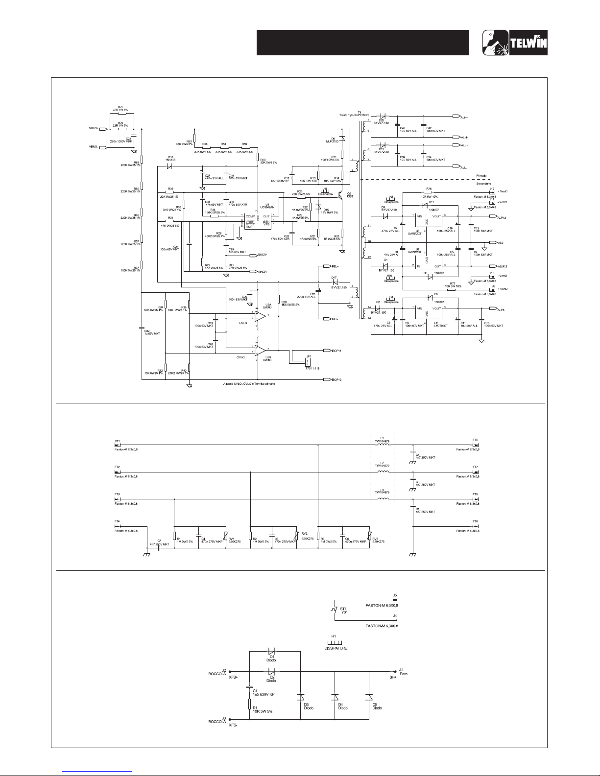
ANALYSIS OF THE BLOCK DIAGRAM Secondary diodes
NOTE: Unless indicated otherwise, it should be assumed Consisting of: D1, D2, D3, D4, D5 (secondary board)
that the components are assembled on the primary N.B. Some versions may have 4 power diodes (D1, D2, D3,
board or machine. D4)
D1 and D2 make the current circulating in the transformer
Block 1 one-way, thus preventing saturation of the nucleus.
EMC Filter D3, D4 and D5 recirculate the inductance output current
Consisting of: C1, C2, C3, C4, C5, C6, C7, L1, L2, L3 (input when the IGBT’s are not conducting, by-passing the
filter board) transformer.
Prevents noise from the machine from being transmitted
along the main power line and vice versa. Block 10
Inductance and shunt
Block 2 Consisting of: L1, R1
Varistor The inductance levels the secondary board diodes’ output
Consisting of: RV1, RV2, RV3 (input filter board) current making it practically continuous/direct. The shunt
Prevents spike noise from the mains, with amplitude reads the current circulating in the inductance and sends it
greater than 400V, from entering the machine. to block 24/25 (amplifier shunt), which will process the
data.
Block 3
Pre-charge Block 11
Consisting of: K1, K2, R3, R9 Secondary EMC Filter
Prevents the formation of high transitory currents that could Consisting of: C1, C2
damage the main power switch, the rectifier bridge and the Prevents noise from the power source from being
electrolytic capacitors. transmitted through the welding cables and vice versa.
When the power source is switched on relays K1 and K2
are de-energised, capacitors C6, C17, C22, C38, C45, C47 Block 12
are then charged by R3 and R9. When the capacitors are Flyback power supply
charged the relays will be energised. Consisting of: U4, Q6,T3, U1, U2, U3
Uses switching methods to transform and stabilise the
Block 4 voltage obtained from block 5 (filter) and supply 2 voltage
Rectifier bridge values of 27V that enable block 13 (driver) to be powered
Consisting of: D19, D10 correctly. It also generates a further three stabilized
Converts the mains alternating voltage into continuous voltages (U1, U2, U3) of -12V, +5V and +12V which are
pulsed voltage. mainly used to power the control board.
Block 5 Block 13
Filter Driver
Consisting of: C6, C17, C22, C38, C45, C47 Consisting of: U1 (opto-insulators board), Q7, Q8 and U2
Converts the pulsed voltage from the rectifier bridge into (opto-insulators board), Q9, Q10.
continuous voltage. Takes the signal from block 12 (flyback power supply) and,
controlled by block 15 (duty cycle maker), makes the signal
Block 6 suitable for piloting block 6 (chopper).
Chopper
Consisting of: Q3, Q4, Q5, Q12, Q13, Q14 Block 14
Converts the continuous voltage from the filter into a high Primary current reader and limiter
frequency square wave (32.5 kHz approx.) capable of Consisting of: D1, R2, R55, R56, R57 R68 (control board)
piloting the power transformer. Picks up and limits the signal from block 7 (current
Regulates the power according to the required welding transformer) and using R68 limits the maximum admissible
current/voltage. primary current. This signal is also scaled down so that it
can be processed and compared in block 15.
Block 7
Current transformer Block 15
Consisting of: T1 Duty cycle maker
The C.T. is used to measure the current circulating in the Consisting of: U2=UC3845 (control board)
power transformer primary and transmit the information to Processes the information from block 16 (adder) and block
block 14 (primary current reader and limiter). 14 (primary current reader and limiter) and produces a
square wave with variable duty cycle limiting the primary
Block 8 current to a maximum pre-set value under all
Power transformer circumstances.
Consisting of:T1
Adjusts the voltage and current to values required for the Block 16
welding procedure, Adder
also forming galvanic separation of primary from Consisting of: U1A, U1B (control board)
secondary (welding circuit from the power supply line). Processes the information from blocks 18, 25, 27, 28 and
3

SUPERIOR 240 CE
sends it to block 15 (duty cycle maker). (control board).
If one of the three input phases is lost this alarm cuts in.
Block 17
Alarm Block Block 25
Consisting of: Q1, D12, D13, R80, Q12 (control board) Shunt Amplifier
When an alarm is detected, the output current is cut off by Consisting of: U4(control board)
operating directly on block 15 (duty cycle maker) in the Amplifies the signal from block 10 (inductance shunt) and
eventof: makes it appropriate for block 26 (maximum current
1) Triggering of thermostatic capsule on secondary board limiter).
dissipator diodes.
2) Triggering of thermostatic capsule on power Block 26
transformer. Maximum current limiter
3) Triggering due to undervoltage.Consisting of: R62 (control board)
4) Triggering due to overvoltage.Processes the information from block 25 (shunt amplifier)
5) Phase loss at input. and, using R62, regulates the maximum welding current to
6) Short circuit at output (electrode holder clamp and earth be supplied by thepower source.
cable connected to each other or electrode stuck to This signal is scaled down so that it can be processed and
piece being welded). compared in l block 16 (adder).
Block 18 Block 27
Potentiometer Function selector
Consisting of: R72 (control board) Consisting of: S1
Used to set the reference voltage needed to adjust the Uses the switch to select the type of welding process: MMA
output current: changes the current from the minimum to ORTIG-LIFT.
the maximum value.
Block 28
Block 19 Short circuit detector
Yellow LED alarm light Consisting of: U3B (control board)
Consisting of: D35 (controlboard) If the welding voltage P is lower than 10V this circuit causes
It is switched on by block 17 (Alarm Block) if an alarm block 30 to trigger (arc force)
occurs.
Block 29
Block 20 Hot Start
Overvoltage safeguard Consisting of: U3D, Q3, C9, Q2 (control board)
Consisting of:U5A, R38, R40 When welding starts this block generates a temporary
If the main supply voltage exceeds the maximum value this overcurrent, which can be adjusted by R72 and is used to
safeguard triggers (a tolerance of approx. ±15% of the pre-heat the electrode in MMA.
power supply voltage is allowed: outside this range the
safeguard triggers). Block 30
Arc Force
Block 21 Consisting of: Q7, C14, Q6 (control board)
Undervoltage safeguard If the arc voltage falls below 10V, this block produces a
Consisting of:U5B, R30, R32 temporary increase in output current, which is used to
If the main supply voltage falls below the minimum allowed detach the electrode from the piece after sticking has
value this safeguard triggers (a tolerance of approx.±15% occurred.
of the power supply voltage is allowed: outside this range
the safeguard triggers). Block 31
Short circuit delay
Block 22 Consisting of: U3A (control board)
Secondary diodes thermostat If output shorting persists, this block switches off the power
Consisting of: thermostatic capsule ST1 source by means of block 17 (alarm block).
When the temperature of the secondary board dissipator
reaches 70°C (approx.) this safeguard triggers. Reset is Block 32
automatic when the cause for alarm is removed. Hot-Start/Arc-Force Potentiometer
Consisting of: R77 (control board)
Block 23 Used to set the reference voltage required to adjust the
Power transformer thermostat strike current percentage (0-100%) (Hot-Start) and the
Consisting of: thermostatic capsule ST2 antistick overcurrent (Arc-Force).
When the temperature of the power transformer is too high
this safeguard triggers. Reset is automatic when the cause Block 33
for alarm is removed. Auxiliary Power Supply
Consisting of: R111, R45, D15 (control board)
Block 24 This block reserves a voltage (about 11Vdc) for the
Phase loss shorting detection circuit so as to detect the shorting at
Consisting of: ISO2, ISO3 opto insulators board, U5C output, if the power is disabled.
4

SUPERIOR 240 CE
Block 34 Block 36
Duty Cycle Limiter Fan
Consisting of: U3C (control board) Consisting of: V1 andV2
Limits the machine duty cycle under loadless operation. Used to cool the power components and is powered by
block 12 (at 12Vdc).
Block 35
Power supply LED
Consisting of: green LED D8 (control board)
Indicates when the machine is correctly powered and
ready to weld.
Input filter board
(1) EMC FILTER
(2)
VARISTOR
(6) CHOPPER (7) CURRENT
TRANSFORMER
(5)
FILTER
(6)
CHOPPER
(13)
DRIVER OPTO
ISOLATOR
(U1,U2, ISO2, ISO3)
Primary board
ILLUSTRATIONS
(4) PRECHARGE
(3) RECTIFIER
BRIDGE
(12) FLYBACK
POWER SUPPLY
(1) EMC FILTER
5

SUPERIOR 240 CE
Control board
Scheda secondario
(9) DIODESECONDARY
(16)
RADER
(18)
POTENTIOMETER
CURRENT
(35)
POWER SUPPLY GREEN LED (19)
YELLOW LED ALARM LIGHT
(27)
FUNCTION
SELECTOR
(26)
MAXIMUM
CURRENT LIMITER
(15) DUTY CYCLE MAKER
(14) PRIMARY CURRENT
READER AND LIMITER
(32)
POTENTIOMETER
HOT-START / ARC-FORCE
Secondary board
(22) SECONDARY
DIODE THERMOSTAT
(9) DIODESECONDARY
6

SUPERIOR 240 CE
General wiring diagram
WIRING DIAGRAM
7

SUPERIOR 240 CE
Wiring diagram primary board - power
Wiring diagram primary board - driver
8

Wiring diagraminput filter board
9
Wiring diagram primary board - power supply
Wiring diagram secondary board
SUPERIOR 240 CE

10
Wiring diagram control board
SUPERIOR 240 CE
Table of contents
Other Telwin Inverter manuals


