PABP USER MANUAL - PRELIMINARY
Photoelectric Amplifier Bus Programmable Series (PABP)
Multiplexed photoelectric amplifier
Website: www.telcosensors.com
V 1.27 Part Number: L40-0666220724
E-Mail: info@telcosensors.com
This device is not to be used for Personnel Protection in Machine
Guarding Safety applications. This device does not include the self-
checking redundant circuitry necessary to allow its use in personnel
machine guarding stand-alone safety applications.
Telco A/S reserves the right to make changes without prior notice
Page 4 of 5
Manual Gain Mode Adjustment
Gain can be adjusted in two large steps with long/ short range selected or continuously with the Manual Gain bar. Maximum gain and long range can be used for most applications and is advised for
applications with contaminated environments e.g. dirt, water and dust.
Chose long range and increase the gain to maximum by sliding the Manual Gain bar to a 100% reading.
More accurate sensitivity adjustment may be required in applications where objects to be detected are small or translucent. Proceed with the following steps:
1 Make sure there is no object present between remote transmitter and receiver sensors.
2 Select long or short range according to application.
3 Increase gain slowly from minimum (0%) until the yellow output indicator changes. Increase a little further until the green Signal OK indicator is on.
4 Select target object with smallest dimensions and most translucent surface.
5 Place target object between remote transmitter and receiver sensors. If the output changes, the gain is adjusted correct. If the output does not change proceed to step 6.
6
Remove the object and decrease the gain by sliding the “Manual Gain Bar” towards 0% until the green Signal OK indicator is off and the LT/LR error indicator flashes simultaneously with red
and yellow light
7
Place target object between remote transmitter and receiver sensors. If the output changes, the gain is adjusted to suit the target but the adjustment is very delicate and not advisable, please
contact your vendor for further information.
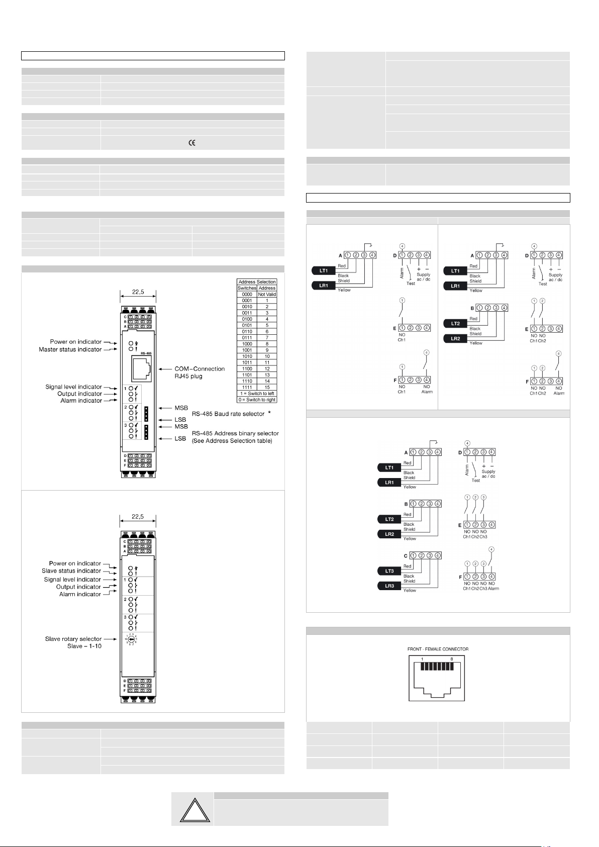
If the signal level is insufficient, the LT/LR error indicator flashes simultaneously with red and yellow light. Check the following:
Check alignment of sensors
Check transmitter and receiver sensors are within sensing range
Check sensor heads are not excessively contaminated
Auto Gain Mode Adjustment
This amplifier automatically compensates for reduction in transmission power due to dirt on sensors, etc, by increasing the transmission power correspondingly. Adjust excess gain with the following
steps:
1 Make sure there is no object present in the beam between remote transmitter and receiver sensors.
2 Turn the slider Excess Gain bar to 3.2 (max excess gain)
3 Wait for regulation indicator to stop blinking, and initialization is finished.
If this never happens, the reason can be that the environment or the sensors are too contaminated, the distance between transmitter and receiver is too large, or the sensors are misaligned.
4 Insert the smallest and most translucent object into the beam. If the output changes, the setting is correct. If the output does not change, proceed with step 5.
5 Remove the object, decrease excess gain slightly by sliding the Excess Gain bar towards 1.5 (lowest excess gain).
If more adjustments have been done and it is not possible to decrease excess gain further, the object cannot be detected with the given setup. Please contact the vendor for further advice.
6 Wait for the regulation indicator to stop blinking (finished new initialization).
7 Go to step 4
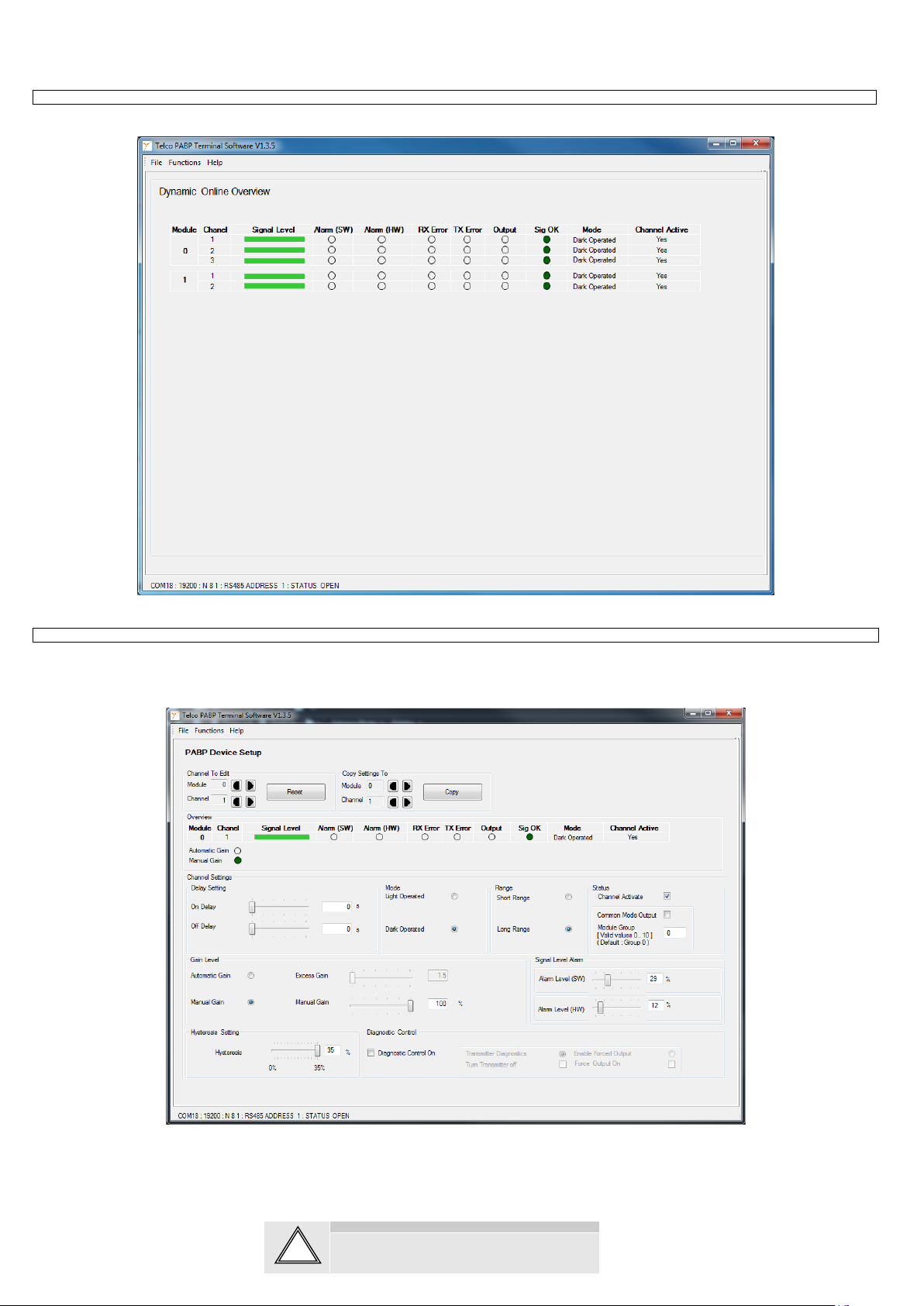
It is possible to manually adjust two alarm levels. Alarm(SW) and Alarm(HW) levels. These are in direct relation to the Signal Level bar so when adjusting the alarm levels means that when the signal
is below that value the alarm is triggered and displayed on the Online Overview and Device Setup. The Alarm(SW) is only triggered in the PABP Terminal Software whereas the Alarm(HW) is
directly related to the Alarm Output pin of the specific PBAP module. If a slave and master are in modules is in common mode a Alarm(HW) will be transferred to the master module Alarm output pin as
well. It is not possible to adjust the alarm levels in Auto Gain mode, as the only alarm associated with Auto gain is the Hardware Alarm. This is only triggered when it is not possible to obtain the wanted
It is possible to manually adjust the hysteresis level of each channel. The range goes from a maximum hysteresis of approx. 35% to no hysteresis of 0%. The hysteresis is related to the maximum
sensing range.
It is possible to turn off the PABPs channels. This is done by unchecking the Channel Activate checkbox. The channel will then be completely ignored by the PABP. If the channel has the Output set
into a Forced output state, this forced state will be still kept and the channel output forced into that state when the channel is turned off.
The On Delay enables output signal to only activate if an object in the detection area is present for the adjusted time period. The Off delay enables output signal to remain activated for the adjusted time
period. The time delay is adjustable between 0-10 s.
Besides the hardware test input which disables the transmitter for all channels on the amplifier, is it also possible to use a test input for each channel on the amplifier. The outputs can also be controlled
individually to be ON or OFF. Doing this will ignore that channel and the rest is still multiplexed. This is all controlled from the Diagnostic Control window. Shown in the next picture.
1 Check the Diagnostic Control On checkbox. The program will come up with a warning textbox and all other controls will be disabled.
2 Either use Test Input, which will test a complete transmitter – receiver chain. This is done by Transmitter Diagnostics, with no objects in the beam.
3 Or Enable Forced Output to manually force the outputs On or OFF. Forced output allows the user to test the outputs even if the beam is blocked.
4 To return to normal mode uncheck the Diagnostic Control On checkbox.
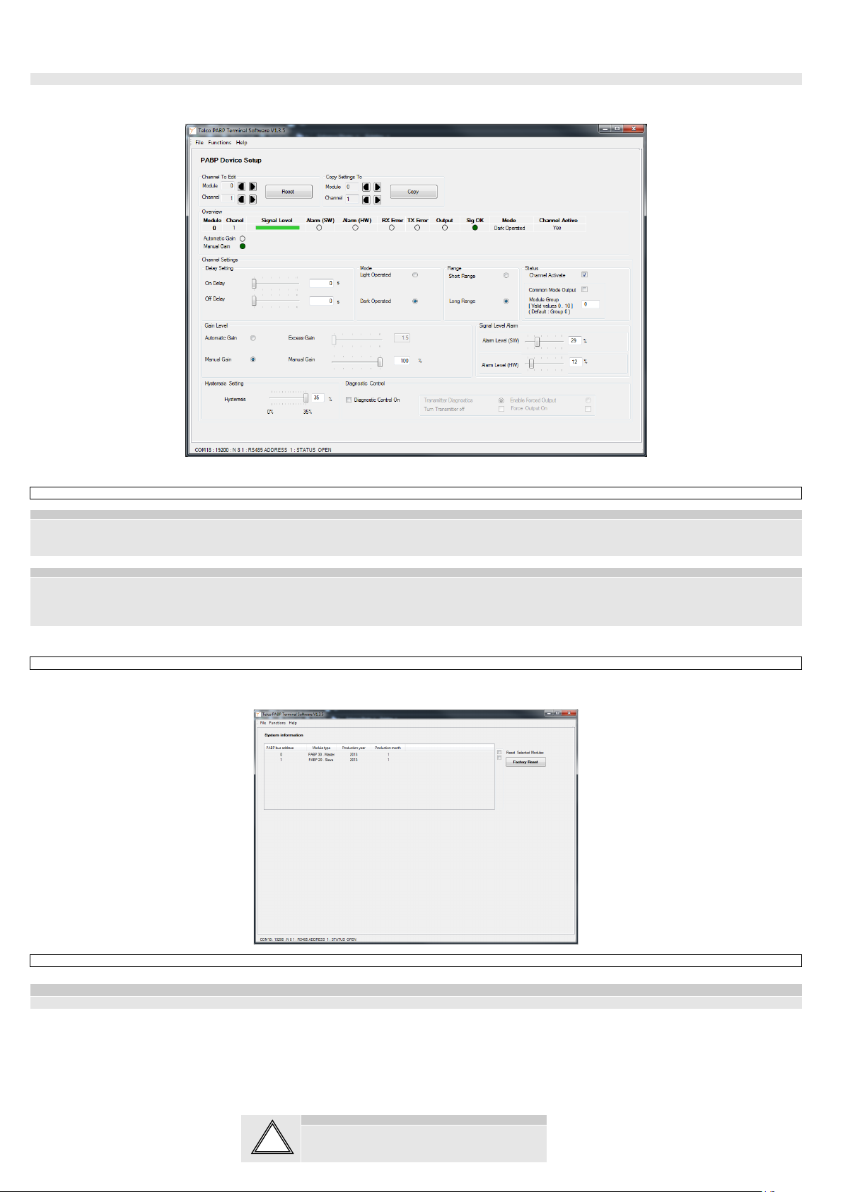
Each channel can be reset to the factory settings by pressing the Reset on the PABP Device Setup page.