TechNexion TEP-0500-IMX6UL User manual

3.1 Cut-out Dimensions
3.2 VESA Mounng
TEP-0500-IMX6UL / TEP-0700-IMX6UL
Quickstart Guide
3 Installaon Instrucons
This secon describes the mounng procedures for TEP series device. The material in the mounng area must
provide sufficient strength for support of this HMI.
This device is compable with VESA MIS-C Standard 35*75mm. There are 4 VESA MIS-C (M4) mounng holes on
the rear side of the device. M4 screws with at least 4mm head-to-p length are required to secure this device.
INNOVATORS OF TECHNOLOGY
TEP-0500-IMX6UL TEP-0700-IMX6UL
TEP-0500-IMX6UL TEP-0700-IMX6UL
2 Dimensions
TEP-0500-IMX6UL TEP-0700-IMX6UL
150.3
105.6
88.2
198.5
136.3
113.9
1 Safety Precauons
Thank you for purchasing a TechNexion TEP series device. This installaon guide will be helpful in the installaon,
wiring and inspecon of your TechNexion HMI. Before using the product, please read this guide to ensure correct
use. You should thoroughly understand all safety precauons before proceeding with the installaon, wiring, and
operaon. Place this instrucon sheet in a safe locaon for future reference. The following suggesons will help
you.
• Keep the device dry. Precipitaon, humidity, and all types of liquids or moisture can contain minerals that will
corrode electronic circuits. If your device does get wet, allow it to dry completely.
• Do not use or store the device in dusty or dirty areas. Its parts and electronic components can be damaged.
• Do not store the device in hot areas. High temperatures can shorten the life of electronic devices, damage
baeries, and warp or melt certain plascs.
• Do not store the device in cold areas. When the device returns to its normal temperature, moisture can form
inside the device and damage electronic circuit boards.
• Do not aempt to open the device.This product needs to be installed by qualified personnel.
• Do not drop, knock, or shake the device. Rough handling can break internal circuit boards and fine mechanics.
• Do not paint the device. Paint can clog the parts and prevent proper operaon.
• Unauthorized modificaons or aachments could damage the device and may violate regulaons governing radio
devices.
• Do not touch any internal or exposed parts of the device as electrical shock may result.
• Do not open the device while power is on. Otherwise electrical shock may result.
• Do not use harsh chemicals, cleaning solvents, or strong detergents to clean the device.
• Be sure the venlaon holes are not obstructed during operaon. Otherwise malfuncon may result due to
bad venlaon or overheang.
These suggesons apply equally to your device, baery, charger, or any enhancement. If any device is not
working properly, take it to the nearest authorized service facility for service.
• Make sure that the available power source matches the required input power of the device. Failure to observe
this cauon may result in electric shock or fire.
• Do not power the unit by DC input when you apply power over the PoE (RJ45).
1.1 Storage and Installaon
1.2 Wiring
1.3 Maintenance and Inspecon
!
136
89
Unit : mm
Unit : mm
179
115
39.5 50.55
1 2
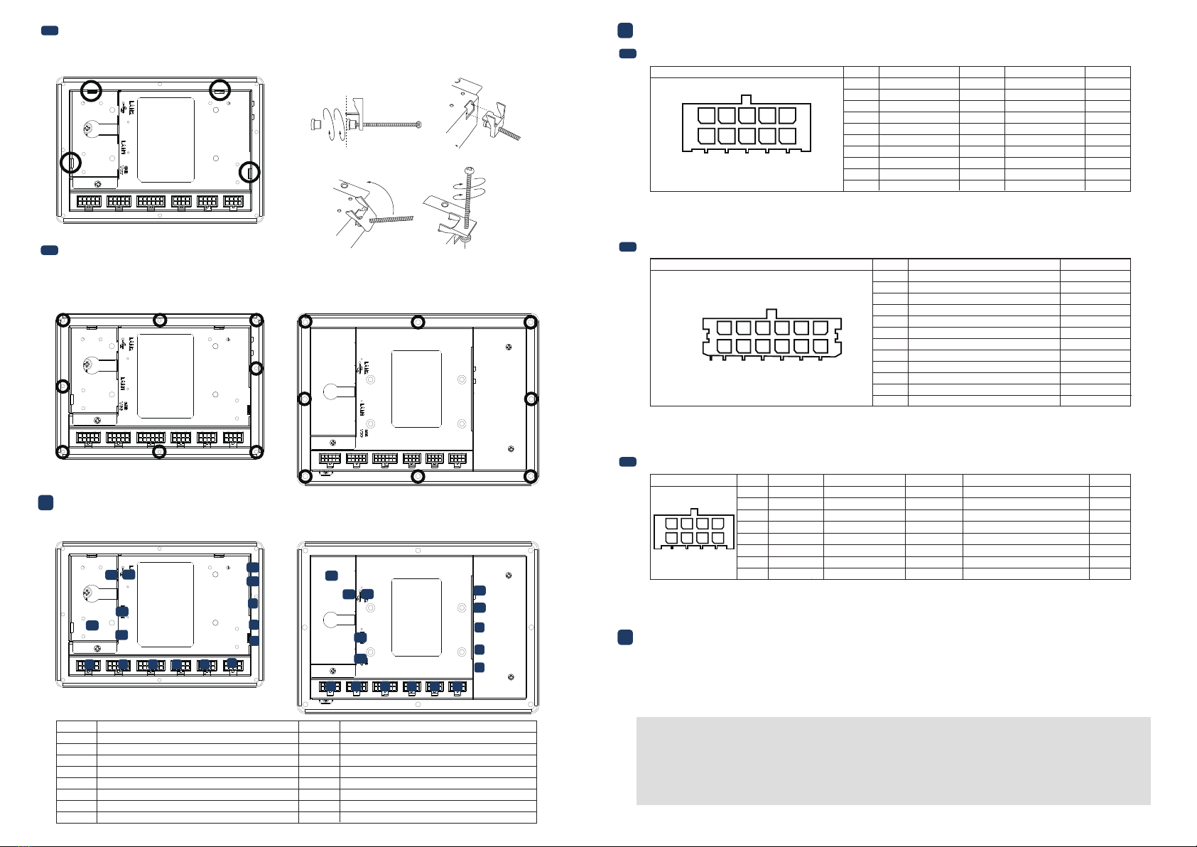
3.3 Rear Mounng and Mounng Clips Installaon (TEP-0500-IMX6UL only)
3.4 Surface Mounng Installaon
4 External Connectors
There are 8 mounng holes (M4) on the rear side of the device required for surface mounng. M4 screws with at
least 5mm head-to-p length are required to secure this device.
There are 5 mounng clips required for rear mounng.
• All Rights Reserved. No part of this document may be photocopied, reproduced, stored in a retrieval system, or transmied, in any
form or by any means whether, electronic, mechanical, or otherwise without the prior wrien permission of TechNexion Ltd.
• No warranty of accuracy is given concerning the contents of the informaon contained in this publicaon. To the extent permied
by law no liability (including liability to any person by reason of negligence) will be accepted by TechNexion Ltd., its subsidiaries or
employees for any direct or indirect loss or damage caused by omissions from or inaccuracies in this document.
• TechNexion Ltd. reserves the right to change details in this publicaon without noce. Please download the most updated version
at: hps://www.technexion.com/support/download-center/
TEP-0500-IMX6UL TEP-0700-IMX6UL
TEP-0500-IMX6UL TEP-0700-IMX6UL
TEP-0500-IMX6UL
1 2 3 4 56
7
8
9
10
11
12 13
14
15
16
1 2 3 4 56
7
8
9
10
11
12 13
14
15
16
Description No.No. Description
1 RS-XXX1 (Serial Port) connector
2 RS-XXX2 (Serial Port) connector
3 CAN Bus connector
4 GPIO1 connector
5GPIO2 connector
6 GPIO3 connector
7MicroSD cardslot
8 USB OTG (Type-C) connector
9LED Light indicator
10 S1 Boot Select button
11 Reset button
12 USB Host connector
13 LAN2 RJ45 connector
14 LAN1 RJ45 and PoE (optional)
15
16
Power Input connector
Grounding screw
Phone: +886-2-82273585
Web: www.technexion.com
16F-5, No. 736, Zhongzheng Road,
ZhongHe District, 23511, New Taipei City, Taiwan
© 2001-2018 TechNexion Ltd.
2018-10-31
5.1 Serial Port Connector (RS-XXX1/RS-XXX2)
5 Pin Definion
Header: Molex 43045-1012 (10-pin Micro-Fit 3.0).
Cable receptacle: Molex 43025-1000 (10-pin Micro-Fit 3.0) plug with crimp contact Molex 43030-0007.
Port Pin # RS-XXX1 Signal Device DeviceRS-XXX2 Signal
1GND GND
2SERIAL1A_TXD ttymxc0 ttymxc2
ttymxc2
ttymxc3
ttymxc3
3SERIAL1A_RXD ttymxc0
4NC
5NC
6 GND
ttymxc17 SERIAL1B_TXD
ttymxc1
8 SERIAL1B_RXD
9 NC
10 NC
SERIAL2A_TXD
SERIAL2A_RXD
NC
NC
GND
SERIAL2B_TXD
SERIAL2B_RXD
NC
NC
12345
678910
5.2 CAN Bus Connector (CANBus)
Header: Molex 43045-1212 (12-pin Micro-Fit 3.0).
Cable receptacle: Molex 43025-1200 (12-pin Micro-Fit 3.0) plug with crimp contact Molex 43030-0007.
GND_CAN
CAN1A_TERM_P can1
CAN1A_P can1
CAN1A_N can1
CAN1A_TERM_N can1
NC
GND_CAN
CAN1B_TERM_P can2
CAN1B_P can2
CAN1B_N can2
CAN1B_TERM_N can2
NC
Port Pin # Signal Interface
1
2
3
4
5
7
6
8
9
10
11
12
123456
789101112
5.3 Digital I/O Connectors (GPIO1/GPIO2/GPIO3)
Header: Molex 43045-0812 (8-pin Micro-Fit 3.0).
Cable receptacle: Molex 43025-0800 (8-pin Micro-Fit 3.0) plug with crimp contact Molex 43030-0007.
Port Pin #
GPIO1/2 Signal
GPIO1/2 Description
GPIO3 Signal
GPIO3 Description Voltage
1 GPIO1A/2A DIG_IN1/OUT1 GPIO2A 3.3V
3.3V
3.3V
3.3V
3.3V
ADCI_INO
2 GPIO1B/2B DIG_IN2/OUT2 GPIO3B PWM_OUT or DIG_IN2/OUT2
3 GND_DIO
Ground for digital I/O
GND_DIO Ground for digital I/O
4 NC NC
5 GPIO1C/2C DIG_IN5/OUT5 GPIO3C PWM_OUT or DIG_IN5/OUT5
6 GPIO1D/2D DIG_IN5/OUT6 GPIO3D PWM_OUT or DIG_IN6/OUT6
7VCC_DIO Supply output VCC_DIO Supply output
8 NC NC
1234
5678
2
1
43
The unit is preloaded with soware that can download and install a selecon of OS images over hardwired
network. Simply connect a network to the unit through the Ethernet LAN RJ45 connector and power it up, then
follow the steps on the screen to load the soware. Local proxies will interfere with this process. For more
informaon, go to our Knowledge Base at: hps://www.technexion.com/support/knowledge-base/
6 Soware Installaon
3 4
This manual suits for next models
1
Other TechNexion Touch Panel manuals


Popular Touch Panel manuals by other brands


IBASE Technology
IBASE Technology ASTUT-152-RE1S user manual

YASKAWA
YASKAWA TP 610C manual

B&R
B&R Power Panel C Series user manual

Beijer Electronics
Beijer Electronics X2 control Hardware and installation manual

AXIOMTEK
AXIOMTEK GOT321W-521 user manual

TRIDONIC.ATCO
TRIDONIC.ATCO x-touchBOX Operation manual


