Tecfluid MT03L Series User manual

R-MI-MT03L Rev.: 2 English version
Instructions manual
The art of measuring
Series MT03L
Electronic converter for level transmitters

2
Thank you for choosing the MT03L converter from MT03 series of
Tecfluid S.A.
This instruction manual allows the installation, configuration and
programming of the electronic converter MT03L. It is recommended
to read it before using the equipment.
• This document shall not be copied or disclosed in whole or in any
part by any means, without the written permission of Tecfluid S.A.
• Tecfluid S.A. reserves the right to make changes as deemed
necessary at any time and without notice, in order to improve the
quality and safety, with no obligation to update this manual.
• Make sure this manual goes to the end user.
• Keep this manual in a place where you can find it when you need
it.
• In case of loss, ask for a new manual or download it directly from
our website www.tecfluid.com Downloads section.
• Any deviation from the procedures described in this instruction
manual, may cause user safety risks, damage of the unit or cause
errors in the equipment performance.
• Do not modify the equipment without permission. Tecfluid S.A. is
not responsible for any problems caused by a change not
allowed. If you need to modify the equipment for any reason,
please contact us in advance.
PREFACE
WARNINGS

3
TABLE OF CONTENTS
1 INTRODUCTION ........................................................................... 5
2 RECEPTION ................................................................................. 5
2.1 Storage temperature ........................................................... 5
3 INSTALLATION ............................................................................. 5
3.1 Location ............................................................................. 5
3.2 Electrical connection ........................................................... 6
3.2.1 Power supply wiring ............................................... 6
3.2.2 Resistance input wiring .......................................... 7
3.2.3 Current input wiring ............................................... 7
3.2.4 Analog output wiring .............................................. 8
3.2.5 Relay output wiring ................................................ 9
4 OPERATION ................................................................................. 11
5 MAIN MENU ................................................................................. 12
5.1 Passwords to access the menus ......................................... 12
6 INSTALLATION PARAMETERS ...................................................... 14
6.1 Language ........................................................................... 15
6.2 Input .................................................................................. 15
6.3 Limits .................................................................................. 15
6.3.1 Capture ................................................................. 15
6.3.2 Distance adjustment .............................................. 16
6.4 Diagnosis ........................................................................... 16
7 PROGRAMMING PARAMETERS .................................................... 17
7.1 Language ........................................................................... 18
7.2 Units .................................................................................. 18
7.3 Decimals ............................................................................ 18
7.4 Damping ............................................................................ 19
7.5 Outputs ............................................................................. 19
7.5.1 Relay 1 and relay 2 ................................................ 19
7.5.1.1 Alarm ...................................................... 19
7.5.1.2 No action ................................................ 20
7.5.2 Analog output ........................................................ 20
7.5.2.1 Programming of the 4-20 mA output .......... 21
7.5.2.2 Current calibration for 4 and 20 mA .......... 21

4
8 SERIAL NUMBER .......................................................................... 21
9 SOFTWARE VERSION ................................................................... 21
10 BRIGHTNESS ............................................................................... 22
11 WORKING SCREEN ...................................................................... 22
12 MAINTENANCE ............................................................................ 22
12.1 Fuse .................................................................................. 22
13 ASSOCIATED SOFTWARE WINSMETER MT03 ............................... 22
13.1 USB cable connection and drivers installation ...................... 22
13.2 Port connection .................................................................. 24
13.3 Access to installation and programming ............................... 24
13.4 Visualization ....................................................................... 26
13.5 Firmware updates ............................................................... 27
14 TECHNICAL CHARACTERISTICS .................................................... 29
15 DIMENSIONS ............................................................................... 30
16 TROUBLESHOOTING .................................................................... 31
5
1 INTRODUCTION
MT03L converters are indicators for level measurement applications.
The electronic circuit is based on the most advanced technology in digital signal processing,
in order to obtain accurate and reliable measurements.
The equipment provides the following features (depending on the model):
• Graphic display with intuitive menus.
• Resistance input compatible with level transmitters series LE and transmitters LTE
from series LT, as well as with most of the level transmitters based in variation of
resistance.
• Analog input 4-20 mA.
• Level indication.
• Current output (4-20 mA) proportional to the level and user programmable.
• Relay outputs user programmable as level alarm..
2 RECEPTION
Converters of series MT03 are supplied conveniently packaged for transportation together
with their instruction manual for installation and operation.
All devices have been verified in our facilities.
2.1 Storage temperature
-20ºC ...... +60ºC
3 INSTALLATION
3.1 Location
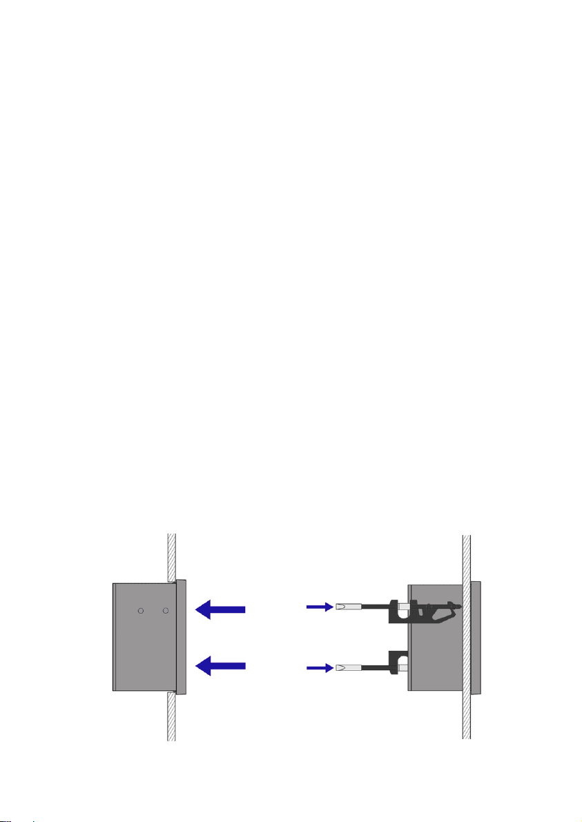
The MT03L converter is housed in a box according to IEC 61554 standard. Its size is 96x96
mm and is intended to be mounted on a panel of a cabinet with a square hole of 90 x 90 mm
+0.5 mm / -0 mm. The cabinet should have a minimum depth of 90 mm behind the panel.
To place it into the cabinet, slide it through the front panel to the bottom as shown in the
following figure. Then screw the clamping arms until exert pressure on the panel.
6
3.2 Electrical connection
The connection of the equipment is via plug-in connectors, polarized to avoid mistakes when
plugged in. The connectors have screw terminals, as per VDE standards, to accept cables with
section of 1.5 mm2.
The pictures of the connections in this manual are always looking at the equipment from the
back.
To help in the wiring of the equipment, the description of the terminals is marked on a label
in the rear side of the device.
For the electrical installation it is recommended to use multiple conductor cables with
individual cable sections in the order of 0.25 to 0.5 mm2in order to make it easier to
connect. It is better to maintain the cables with mains voltage (power supply) separated from
the cables with low level signals (4-20 mA, etc.).
To connect the cables, peel the outside insulation to free the inner cables. It is
recommended to put a terminal at the ends of the wires to avoid loose ends.
Then, screw the wires into the corresponding positions in the female aerial connector.
Finally, place each connector with its corresponding male connector on the rear side of the
converter.
IMPORTANT NOTE: In order to comply with the electrical safety requirements as per EN-
61010-1 (IEC 1010-1), the installation of the equipment must take into account the following:
• The equipment must be installed in the front panel of an electrical mounting cabinet,
leaving only the front of the equipment accessible to the operator.
• In case of AC power supply, a mains switch must be provided to disconnect the
equipment. This switch must be marked as the disconnecting device for the
equipment and be within easy reach of the operator.
• The housing must not be opened when the instrument has mains supply
connected.
IMPORTANT NOTE: To ensure smooth operation of the equipment, it is recommended to
make the connection paying attention to the following points:
• For the output signals, use shielded cable when possible.
• Keep the cables away from strong sources of noise.
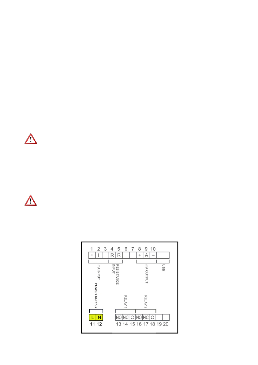
3.2.1 Power supply wiring
7
Before starting the wiring of the instrument, check that the supply voltage available is the
same as marked on the label of the converter.
Terminal Power supply AC Power supply DC
11 Phase DC
12 Neutral DC
In case of DC power supply, the equipment is provided by a diode bridge that allows
connecting it regardless of the polarity.
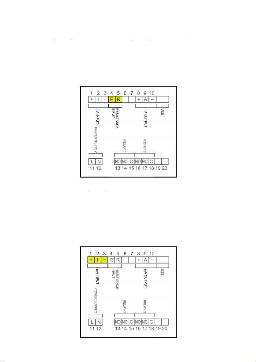
3.2.2 Resistance input wiring
Terminal
4 Resistance
5Resistance
This input is compatible with level transmitters of series LE and transmitters LTE of series LT,
as well as with other level transmitters based on resistance variation with values between 0
and 6500 Ω.
3.2.3 Current input wiring
8
3.2.4 Analog output wiring
Terminal
1 mA (positive, power supply for a passive device)
2mA input
3 mA (negative, input from an active device)
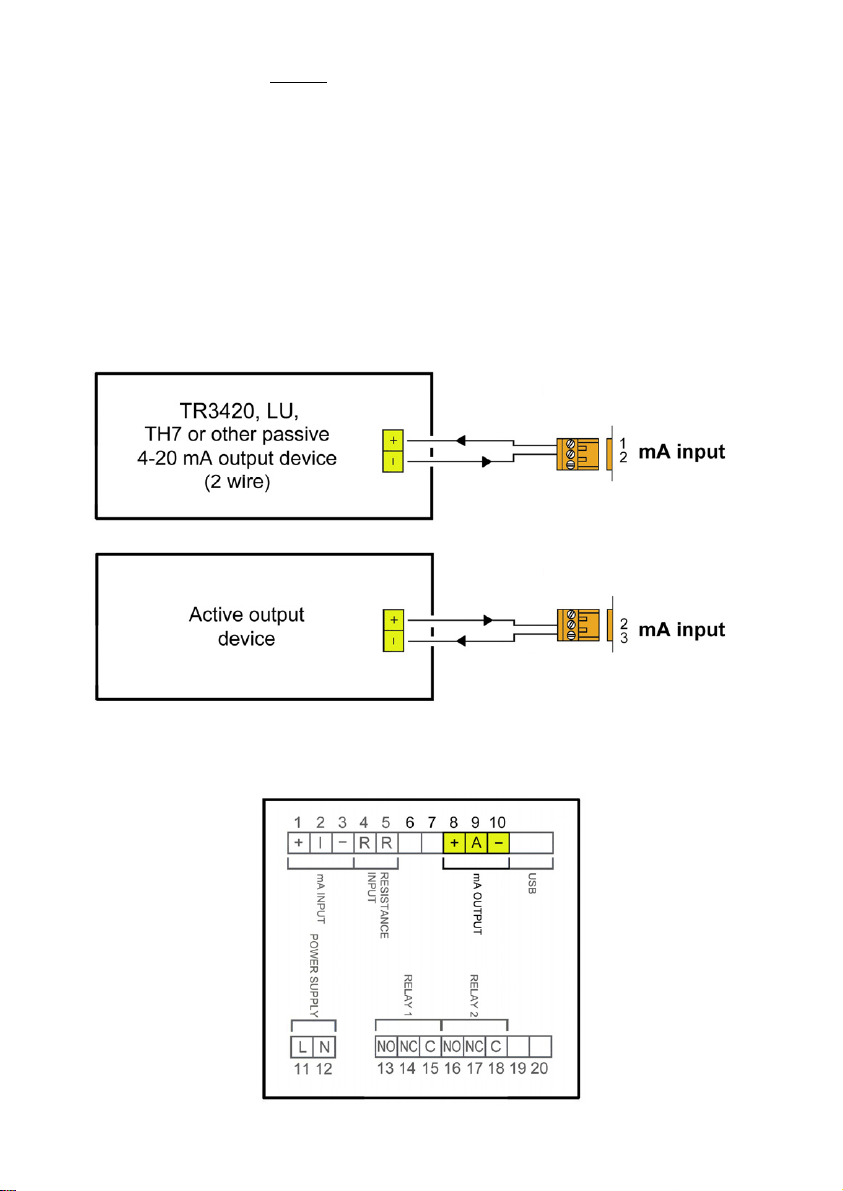
This input is compatible with any flow rate transmitter that provides a 4-20 mA output.
The impedance is 120 Ω. The input has a protection in order to limit the voltage applied to
the circuit.
In the event that the current transmitter is passive, for example a 2-wire transmitter, it is
necessary to power the current loop. It is done by connecting the transmitter to terminals 1
and 2.
If the current transmitter is active, the connection is between terminals 2 and 3.
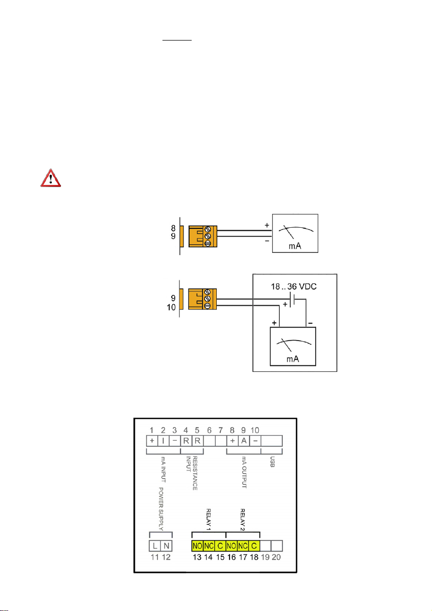
9
3.2.5 Relay output wiring
Terminal
8mA (positive, active output)
9mA
10 mA (negative, passive output)
The analog output is galvanically isolated. It can be either active (which means that the
receiving device must be passive) or passive (which means that the receiver must supply the
power for the current loop). It is recommended to use a receptor with an input resistance of
less than 700 to guarantee correct operation.
The configuration of the analog output mode (active or passive) is done by means of the
connection to the terminal strip. For active mode, terminals 8 and 9 are connected. For
passive mode, terminals 9 and 10 are connected.
NOTE: The analog output has a protection against reversed polarity. Due to another
protection against over voltages, if a loop supply voltage of more than 36 V is connected the
equipment may be damaged.
Active output
Passive output
10
Terminal Description Relay
13 Normally open Relay 1
14 Normally closed Relay 1
15 Common Relay 1
16 Normally open Relay 2
17 Normally closed Relay 2
18 Common Relay 2
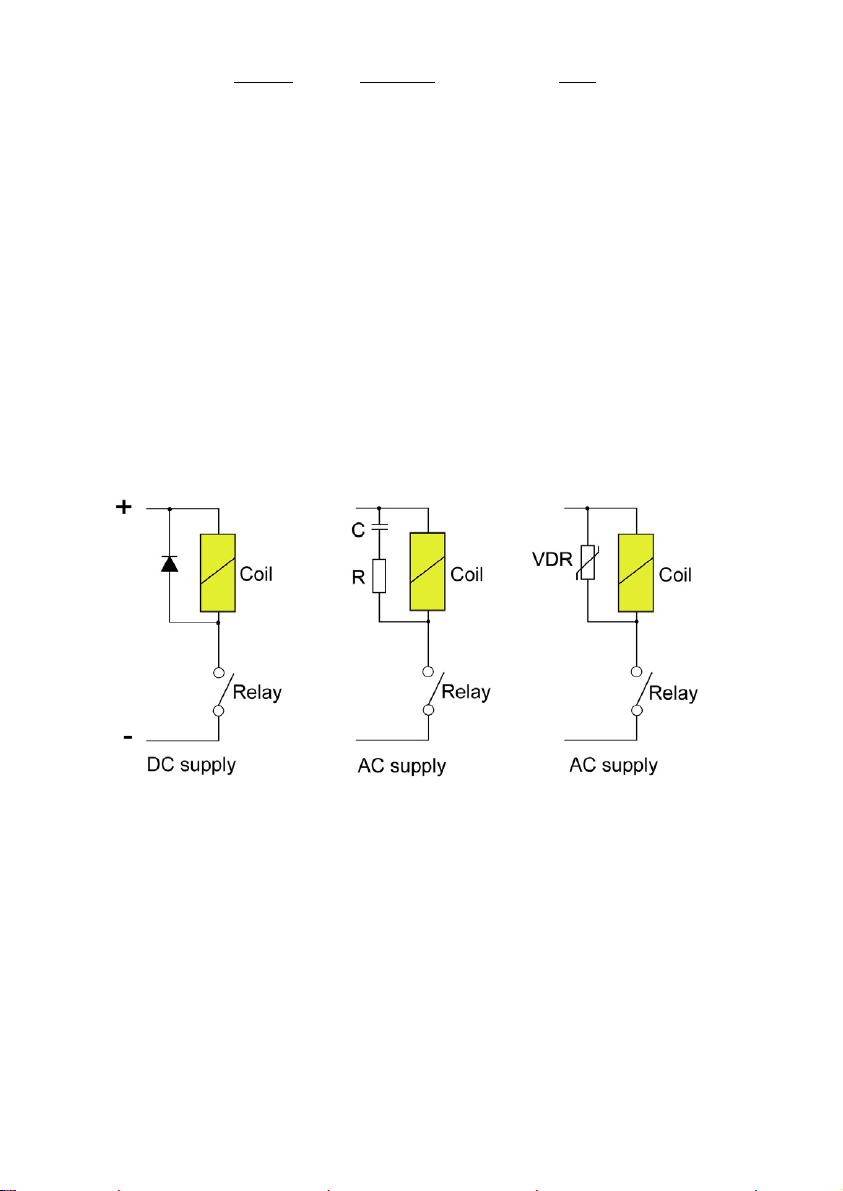
The relay outputs provide relays with potential free contacts (see characteristics on page 29).
The status of the relay contacts corresponds to the relay at rest.
The relay contacts are not protected in any way, and therefore they must be installed
externally as required in the application, taking into account the limitations of the
characteristics of such contacts.
In the case of having inductive loads, and to extend the working life of the relay contacts, it is
recommended to use overvoltage protection (VDR for AC and diodes for DC loads). In all
cases a fuse or some kind of protection against short circuits, should always be provided
according to the needs of the intended load.
Table of contents
Other Tecfluid Media Converter manuals


