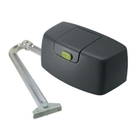
TdA ZK300DC User manual

Swing Gate Operator
ZK300DC
Installation and Users Manual
Total Door Automation (Australia) Pty Ltd
www.totaldoorautomation.com.au
sales@totaldoorautomation.com.au
Technical Support 1800 AUSTDA (1800 287 832)
WARNING
ONLY QUALIFIED AND EXPERIENCED
TECHNICIANS SHOULD ATTEMPT INSTALLATION
OR SERVICE TO THIS UNIT, OTHERWISE, SERIOUS
PERSONAL INJURY, DEATH, OR PROPERTY
DAMAGE MAY OCCUR.
SAVE THESE INSTRUCTIONS.

ZK300DC SWING GATE OPERATOR USER’S MANUAL
2
TABLE OF CONTENTS
Important Safety Information 3
Additional Features 3
Packing List 4
Specifications 5
Necessary Tools 5
Site Preparation 5
Mechanical / Installation 6
Electrical / Control Box Mounting 12
Electrical / Main Terminal Wiring 13
Electric Lock 14
Flashing Light 14
External Button Switch 14
Infrared Photocell 14
Battery 14
Electrical / Setting 15
Learn Remote Controls 15
To Erase All Remote Controls 15
Setting Open and Close Limit 15
Setting Auto Close Time 15
Setting Interval Time 15
Setting obstruction force 15
Maintenance 16
Troubleshooting 16

ZK300DC SWING GATE OPERATOR USER’S MANUAL
3
1. Important Safety Information
Please read these important safety instructions and follow all instructions as
incorrect installation can lead to severe injury/death or property damage:
DISCONNECT the power from the MAINS before making any repairs or removing its
covers. ONLY experienced service gate installer can install the gate and control unit.
Drive through the gate system only after complete opening.
DO NOT operate the gate operator unless the gates are in full view and free from
objects such as cars and children/people. SERIOUS PERSONAL INJURY and/or
property damage can result from failure to follow this warning.
The gate must be WELL BALANCED. Sticking or binding gate must be repaired by an
experienced service gate installer prior to Opener installation.
DO NOT allow control devices to be placed so that a person can access them by
reaching through the gate.
NEVER active your gate operator until you ensure that the area is clear of people,
pets or other obstructions.
When using the auto close mode, a PHOTOELECTRIC BEAM must be correctly fitted
and correctly tested for operation at regular intervals. EXTREME CAUTION is
recommended when using the Auto close mode. All the safety rules must be followed.
NEVER mount any device that operates the gate operator where the user can reach
over, under, around or through the gate to operate the controls.
We strongly recommend the use of PHOTOELECTRIC BEAM to provide ADDITIONAL
SAFETY PROTECTION.
Failure to comply with the instructions above may result in personal injury/death or
property damage. Our company does not accept responsibility for damage or injury
resulting from installing this operator.
2. Additional Features
One drive operator for single gate installation, and two drive operators for dual gate
installation.
Supports up to 40 remote control transmitters, (2 transmitters included in the
packing)
User programmable and user erasable remote codes.
Remote control hopping code technology prevents your remote code being accessible
to others.
For safety protection, ZK300DC will stop if it encounters an obstruction during closing
or opening.
Manual key release design for emergency purposes.

ZK300DC SWING GATE OPERATOR USER’S MANUAL
4
3. Packing List
After receiving the product, you should make an unpack-inspection, in which you should
check whether the product was damaged. If you have any problem please contact dealer.
Table 1 Packing List of ZK300DC Swing Gate Operator
Item
Diagram
Quantity
Remark
For one
drive
operator
For two
drive
operators
Gate Operator
1
2
In the same box.
Post bracket
1
2
Gate bracket
1
2
Accessories
Pin
2
4
Nut
2
4
Screw M6X16
2
4
Nut M6
2
4
Spring washer
2
4
Screw M8X25
2
4
Nut M8
2
4
Spring washer8
2
4
Level gauge
1
1
User’s manual
1
1
Release Key
1
2
Control box
+2 remotes
1
1
Stop block
1
2
Optional
Electric lock
1
1
Optional
Base plate
1
1
Optional

ZK300DC SWING GATE OPERATOR USER’S MANUAL
5
4. Specification
Table 2 Technical data
5. Necessary Tools
The following tools may be necessary to install the ZK300DC operator. You will need an
electric drill, hacksaw, screwdrivers, tape measure, multimeter, level, wire cutters and wire
stripper, a socket set, and possibly access to a welder if your installation cannot use the
supplied brackets. If the brackets included do not fit your gate because of the dimensions
of your gate, you may have to fabricate brackets for your application or notch a column in
order to obtain the necessary set back.
6. Site Preparation
Before commencing installation, check the following:
The gate moves freely by hand for the full length of open and close travel.
Check that the structure is sufficiently strong and rigid, the operator must operate on
a reinforced point on the gate and that its dimensions and weights conform to those
listed in the specifications of this document.
The gate should be mounted to the fence post and swinging freely, there should be
little resistance in the swing of the gate.
Make sure that the gate is plumb and level.
The fence posts must be mounted in concrete.
If you want to use electric lock, make sure the bottom of the gate is 45-50mm from
the ground. If the electric lock is not required, make sure the distance from the
bottom of the gate to the ground more than 20mm.
In order to protect the wires, between the gate operator and the control box,
armored cable, galvanized cable or PVC conduit must be set into the concrete when
it is poured. The diameter of the cable must be more than 20mm.
Wires within the cable shall be located or protected so that no damage can result
from contact with any rough or sharp part.
Power supply
AC240V, 50Hz
Motor
DC24V 50W
Rated force
1000N
90 opening or closing
time (one gate)
20 seconds
Max. gate weight
300kg
Max. gate width
9.8 feet (3 meters)
Working angle of gate
90or 105
Limit switch
Encoder
Ambient temperature
-15ºC~+50ºC
Battery
3.5Ah, 24V

ZK300DC SWING GATE OPERATOR USER’S MANUAL
6
Use another cable for safety devices (such as electric lock, infrared photocell, flashing
light, external button switch etc.), electrical lock wire should be more than 1.5mm2,
and the other wires should be more than 0.5 mm2.
To prevent rainwater from entering into the cable, arrange the cable as show in Fig.1.
Fig.1
7. Mechanical / Installation
Main structure and dimension
1
2
34
5
6
7
7、Gate bracket
6、Release nut
5、Lead screw
4、DC Motor
3、Post bracket
2、End joint
1、Connector
Fig.2
Fig.3
315840
1 0 0
60.5

ZK300DC SWING GATE OPERATOR USER’S MANUAL
7
To release the operator by turning the release nut anticlockwise.
The gate is mounted on one face of the mounting post, and the operator is mounted on the
face 90 degrees from it. Below is schematic of push to open configurations.
As shown in the diagram below, correctly mounting geometry assures that the desired
degrees of swing are achieved, that the gate speed is correct, and that the operator and
gate will operate properly and have a long life.
A
B
α
Hinge
Post
Post bracket
Gate bracket
105°
90°
50
50130
115150
135
αCmaxBA
Cmax
>0°
>0°
D
E
D E
110
110
975
974
5-10mm
Stop block
(Open position)
Base plate
(close position)
>100
Fig.4 Pull to open mounting geometry
Install automatic gate operator (see Fig.5)
Locate the gate operator between the two hinges, the installation height range is 300 –
800mm. this will prevent the gate from twisting and flexing. Add a cross bar on the gate if
necessary.
Note: If the operator is mounted at a height above the specified range, and the gate is not
sturdy enough, then it may result in bending or damage to the gate and gate operator.

ZK300DC SWING GATE OPERATOR USER’S MANUAL
8
Fig.5
Rear parts of gate operator
Fix the post bracket on the cement pillar with screws and spacers (or welding for
metal pillar). Make sure that the bracket is plumb and lever.
Mount the rear part of the gate operator on the post bracket using the pin supplied,
secure the pin using the nut. See Fig. 7.
The bracket installation should meet the specifications as shown in figure 4.
Fig.6
Screw
Washer
and nut
1 2 3 4 5 6

ZK300DC SWING GATE OPERATOR USER’S MANUAL
9
Fig.7
Front parts of gate operator
Move the front part of gate operator up and down slowly, check the installation height
of the gate bracket, fit the gate bracket to the gate, and use a level meter to check
the flatness of the operator (See Fig.9). Tack weld the gate bracket on the gate,the
bracket installation should meet the specifications as shown in Fig.4.
Release the gate operator, open and close the gate manually, performing complete
opening and closing travel. Movement must be smooth.
If this is not the case, review bracket positioning and that its dimensions conform to
those listed in the specifications of this document.
After you have identified the desired position of the bracket, remove the gate
operator, fix or weld the gate bracket on the gate permanently. See Fig.9.
Mount the front part of gate operator on the bracket using the pin and nut supplied.
See Fig.8.

ZK300DC SWING GATE OPERATOR USER’S MANUAL
10
Fig.8
Fig.9
Release function
After installing the brackets, loose the release nut by turning the key about 5 circles
anticlockwise, make sure that the release nut can not be pulled out. Manually open or close
the gate, review bracket positioning and that its dimensions conform to those listed in the
specifications of this document. After adjusting, tighten the release nut clockwise, then
rotate the steel tube by hand until the tube is clamped (meanwhile, the tube is click), finally
tighten the release nut firmly.
Fig.10
Level
Table of contents
Other TdA Gate Opener manuals