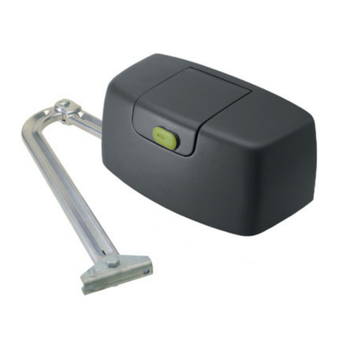
tau 700BOXR18CT User manual

CASSA DI FONDAZIONE R18 / R18 FOUNDATION BOX / FUNDAMENTKASTEN R18
CAISSE DE FONDATION R18 / CAJA DE CIMENTACIÓN R18
WARNING!
IT - ATTENZIONE: TUTTI I CAVI ELETTRICI NON DEVONO ESSERE GIUNTATI ALL’INTERNO DEL MOTORE, SE NECES-
SARIO, USARE L’APPOSITO CONNETTORE STAGNO OPTIONAL GS5 / GS3 A SECONDA DEL MODELLO. TAU SRL
NON SI ASSUME LA RESPONSABILITÀ DEI DANNI CAUSATI DALLE INFILTRAZIONI DI ACQUA ALL’INTERNO
DEI GIUNTI ERRATI. IL CAVO IN DOTAZIONE È DI LUNGHEZZA ADEGUATA PER EFFETTUARE I COLLEGAMENTI
ALL’INTERNO DI SCATOLE DI DERIVAZIONE O DEL QUADRO DI COMANDO.
GB - WARNING: ALL ELECTRIC CABLES MUST NOT BE SPLICED INSIDE THE OPERATOR. IF NECESSARY, USE THE
SPECIAL OPTIONAL WATERPROOF CONNECTOR GS5 / GS3 (DEPENDING UPON THE MODEL). TAU SRL DOES
NOT TAKE RESPONSIBILITY FOR DAMAGES CAUSED BY WATER SEEPING THROUGH WRONG JOINTS. THE SUP-
PLIED CABLE IS LONG ENOUGH TO MAKE CONNECTIONS INSIDE JUNCTION BOXES OR CONTROL BOARDS.
DE - WARNUNG: ALLE ELEKTRISCHEN KABEL DÜRFEN NICHT IM MOTOR VERBUNDEN WERDEN. FALLS ERFOR-
DERLICH, VERWENDEN SIE JE NACH MODELL DIE OPTIONALE WASSERDICHTE STECKVERBINDUNG GS5 / GS3.
TAU SRL ÜBERNIMMT KEINE VERANTWORTUNG FÜR SCHÄDEN, DIE DURCH WASSERINFILTRATION IN DEN
FALSCHEN VERBINDUNGEN VERURSACHT WERDEN. DAS MITGELIEFERTE KABEL HAT EINE AUSREICHENDE
LÄNGE, UM DIE ANSCHLÜSSE INNERHALB DER ANSCHLUSSDOSEN ODER DER STEUERUNG AUSZUFÜHREN.
FR - AVERTISSEMENT: TOUS LES CÂBLES ÉLECTRIQUES NE DOIVENT PAS ÊTRE ÉPISSÉS À L’INTÉRIEUR DU MOTEUR.
SI NÉCESSAIRE, UTILISEZ LE CONNECTEUR ÉTANCHE SPÉCIAL EN OPTION GS5 / GS3 (SELON LE MODÈLE). TAU
SRL N’ASSUME AUCUNE RESPONSABILITÉ POUR LES DOMMAGES CAUSÉS PAR L’INFILTRATION D’EAU DANS
LES MAUVAIS JOINTS. LE CÂBLE FOURNI EST SUFFISAMMENT LONG POUR EFFECTUER LES CONNEXIONS À
L’INTÉRIEUR DES BOÎTES DE JONCTION OU DE LA CENTRALE DE COMMANDE.
ES - ADVERTENCIA: TODOS LOS CABLES ELÉCTRICOS NO DEBEN SER EMPALMADOS ADENTRO DEL MOTOR; SI ES
NECESARIO, UTILICE EL CONECTOR ESPECIAL A PRUEBA DE AGUA GS5 / GS3 SEGÚN EL MODELO. TAU SRL NO
SE RESPONSABILIZA POR LOS DAÑOS CAUSADOS POR LA INFILTRACIÓN DE AGUA DENTRO DE LAS JUNTAS
EQUIVOCADOS. EL CABLE SUMINISTRADO ES LO SUFICIENTEMENTE LARGO PARA HACER LAS CONEXIONES
DENTRO DE LAS CAJAS DE CONEXIONES O DEL PANEL DE CONTROL.
NONOYESYES
TAU srl - Via Enrico Fermi, 43 - 36066 Sandrigo (VI) - Italy
Tel +39 0444 750190 - www.tauitalia.com D-MNL0BOXR18
13-06-22 - Rev.00
700BOXR18CT - 700BOXR18I
Foglietto illustrativo - CARTA - Raccolta dierenziata . Segui le indicazioni del tuo comune.
Instruction leaet - PAPER - Waste separation. Follow the instructions of your city hall
22
PAP

161
155
190
66
130
414
64
50
14.7130
190
335
45.3
392
DESCRIZIONE TECNICA / TECHNICAL DESCRIPTION / TECHNISCHE BESCHREBUG
DESCRIPTION TECHNIQUE / DESCRIPCION TECNICA.
italiano english deutsch francais español
Leve di trasmissione
zincate.
Cassa di fondazione:
lamiera in cataforensi /
acciaio inox
Galvanised drive
levers.
Foundation box: sheet
metal powder coated
/ Stainless steel
Verzinkte
antriebshebel.
Fundamentkasten:
KTL-beschichtes Blech
/ Edelstahl
Leviers de transmis-
sion Zingués.
Caisse de fondation:
tôle traitée par catapho-
rèse / acier inox
Palancas de trasmisión:
galvanizadas.
Caja de fundación:
chapa en cataforesis /
acero inoxidable
MISURE D’INGOMBRO / OVERALL DIMENSION / ABMESSUNGEN UBER ALLES
DIMENSIONS D’ENCOMBREMENT / MEDIDAS EXTERIORES MÁXIMAS
LIVELLO
PAVIMENTO
FINITO
5
34
1
130 52
66
18.5
2
g./Abb. 2
italiano
english
ISTRUZIONI PER IL MONTAGGIO
1) Vericare l’ecienza delle parti sse e mobili della struttura che sarà automatizzata.
2) Eseguire lo scavo sulla base delle misure riportate in g.2.
3) Collocare la cassa di fondazione (1 g.2) all’interno dello scavo, in modo che il foro per l’albero d’uscita del motore sia in asse con il cardine
superiore del cancello (g.2).
4) Posizionare il motoriduttore nella cassa e bloccarlo con le 4 viti forniti unitamente ad esso.
5) Inserire un tubo per il drenaggio dell’acqua utilizzando il foro praticato sulla cassa (3 g.2).
6) Inserire una guaina spiralata per il passaggio dei cavi motore usando il foro sulla cassa (4 g.2).
7) Gettare (il calcestruzzo) all’interno dello scavo; curare la messa in bolla della cassa che deve sporgere dal livello del pavimento nito di 3 mm
(= spessore del coperchio - 2 g.2).
8) Montare tutti gli organi di collegamento.
9) Saldare l’anta al gruppo (5 g.2).
ATTENZIONE: se il peso del cancello è posato direttamente sulla cassa di fondazione, ogni 200.000 cicli cambiare la bronzina.
ASSEMBLY INSTRUCTIONS
1) Check that the xed and moving parts of the structure which is to be automated are in good working order.
2) Dig the hole, carefully adhering to the measurements shown in Figure 2.
3) Place the foundation box (1 Figure 2) in the hole, in such a way that the opening for the motor output shaft runs along the same axis as the
upper hinge of the gate (Figure 2).
4) Place the gearmotor in the box and fasten it using the 4 screws supplied.
5) Insert a drainpipe through the hole in the box (3 Figure 2).
6) Insert a spiral sheath for the passage of the motor cables through the hole in the box (4 Figure 2).
7) Lay (the concrete) in the hole and carefully align the box which must protrude to 3 mm above the level of the nished ooring (= cover
thickness - 2 Figure 2).
8) Assemble all the connection components.
9) Weld the leaf to the group (5 Figure 2).
CAUTION: If the weight of the gate is placed directly on the foundation box, the bush needs to be replaced every 200,000 cycles.
g./Abb. 1

deutsch
français
español
g./Abb. 3
LIMITI D’IMPIEGO / OPERATIONAL LIMITS / EINSATZGRENZEN / LIMITES D’EMPLOI / LÍMITES DE EMPLEO
MONTAGEANWEISUNGEN
1) Die Ezienz der festen und beweglichen Teile der zu automatisierenden Struktur überprüfen.
2) Die Ausgrabung nach den Maßen in Abb. 2 durchführen.
3) Den Fundamentkasten (1, Abb. 2) in der Ausgrabung so anbringen, dass das Loch für die Motorausgangswelle mit dem oberen Angelzapfen
des Tors geuchtet ist (Abb. 2).
4) Den Getriebemotor im Kasten anbringen und mit den 4 mitgelieferten Schrauben befestigen.
5) Einen Drainageschlauch für das Wasser einfügen, hierzu das Loch am Kasten verwenden (3, Abb. 2).
6) Einen Spiralmantel für die Durchführung der Motorkabel einfügen, hierzu das Loch am Kasten verwenden (4, Abb. 2).
7) In Beton versenken und auf die Nivellierung des Fundamentkastens achten, der 3 mm über den fertigen Fußboden herausragen muss (= Dicke des
Deckels – 2, Abb. 2).
8) Alle Verbindungselemente montieren.
9) Den Torügel an der Gruppe anschweißen (5, Abb. 2).
ACHTUNG: Wenn das Gewicht des Tors direkt auf dem Fundamentkasten gelegt wird, das Bronzelager alle 200.000 Zyklen wechseln.
INSTRUCTIONS POUR LE MONTAGE
1) Vérier l’ecacité des parties xes et mobiles de la structure destinée à être automatisée.
2) Creuser le trou sur la base des mesures indiquées dans la g.2.
3) Placer la caisse de fondation (1 g.2) dans le trou, de manière que le trou pour l’arbre de sortie du moteur se trouve dans l’axe du gond
supérieur du portail (g.2).
4) Positionner le motoréducteur dans le caisson de fondation et le bloquer avec les 4 vis fournies.
5) Introduire un tube pour le drainage de l’eau en utilisant le trou sur le caisson (3 g.2).
6) Introduire une gaine spiralée pour le passage des câbles moteur en utilisant le trou sur le caisson (4 g.2).
7) Couler le ciment à l’intérieur du trou ; veiller à mettre de niveau le caisson qui doit dépasser du niveau du sol ni de 3 mm (= épaisseur du
couvercle - 2 g.2).
8) Monter tous les organes de liaison.
9) Souder le battant au groupe (5 g.2).
ATTENTION: Si le poids du portail est placé directement sur la caisse de fondation, le palier doit être remplacé tous les 200 000 cycles.
INSTRUCCIONES PARA EL MONTAJE
1) Verique la ecacia de las partes jas y móviles de la estructura que se automatizará.
2) Efectúe la excavación basándose en las medidas que se indican en la g.2.
3) Coloque la caja de cimentación (1 g.2) en el interior de la excavación, de forma que el oricio para el eje de salida del motor se encuentre
en línea con el gozne superior de la cancela (g.2).
4) Coloque el motorreductor en la caja y bloquéelo con los 4 tornillos que se entregan junto con el motorreductor.
5) Introduzca un tubo para el desagüe del agua utilizando el oricio efectuado sobre la caja (3 g.2).
6) Introduzca una vaina helicoidal para pasar los cables del motor utilizando el oricio sobre la caja (4 g.2).
7) Tire (el hormigón) en el interior del agujero; es necesario que coloque la caja de forma que sobresalga del nivel del suelo acabado unos 3
mm (= grosor de la tapa - 2 g.2).
8) Monte todos los órganos de conexión.
9) Suelde la hoja al grupo (5 g.2).
ATENCIÓN! Si el peso è del porton se coloca directamente en la caja de fundacion, cada 200000 ciclos cambiar el cojinete/rodamiento.

Via Enrico Fermi, 43 - 36066 Sandrigo (VI) - Italy
Tel +39 0444 750190 - Fax +39 0444 750376
[email protected] - www.tauitalia.com
Foglietto illustrativo
CARTA - Raccolta dierenziata. Segui le indicazioni del tuo comune. (N.B.: togliere i punti metallici)
Instruction leaet
PAPER - Waste separation. Follow the instruction s of your city hall. (Note: remove the staples)
22
PAP
This manual suits for next models
1
Table of contents
Other tau Gate Opener manuals