T&C TC30 User manual

PART# TC30.NG01.C
For TC30 Series C
IMPORTANT:
THESE INSTRUCTIONS ARE TO REMAIN
WITH THE HOMEOWNER
These instructions are supplementary to the Installation
and Operating Instructions supplied with the replace
and should be kept together. Refer to the Installation
and Operating Instructions for proper gas supply, safety
requirements and operating instructions.
TC30 CHALET
BURNER KIT
INSTRUCTIONS
140708-16 TC30.NG01.C 5056.429.01

2
TC30.NG01.C 140708
Notes
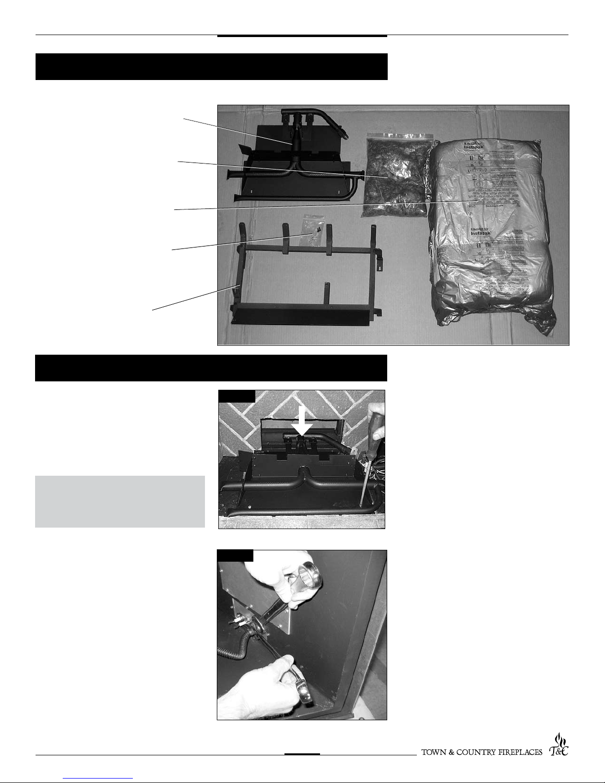
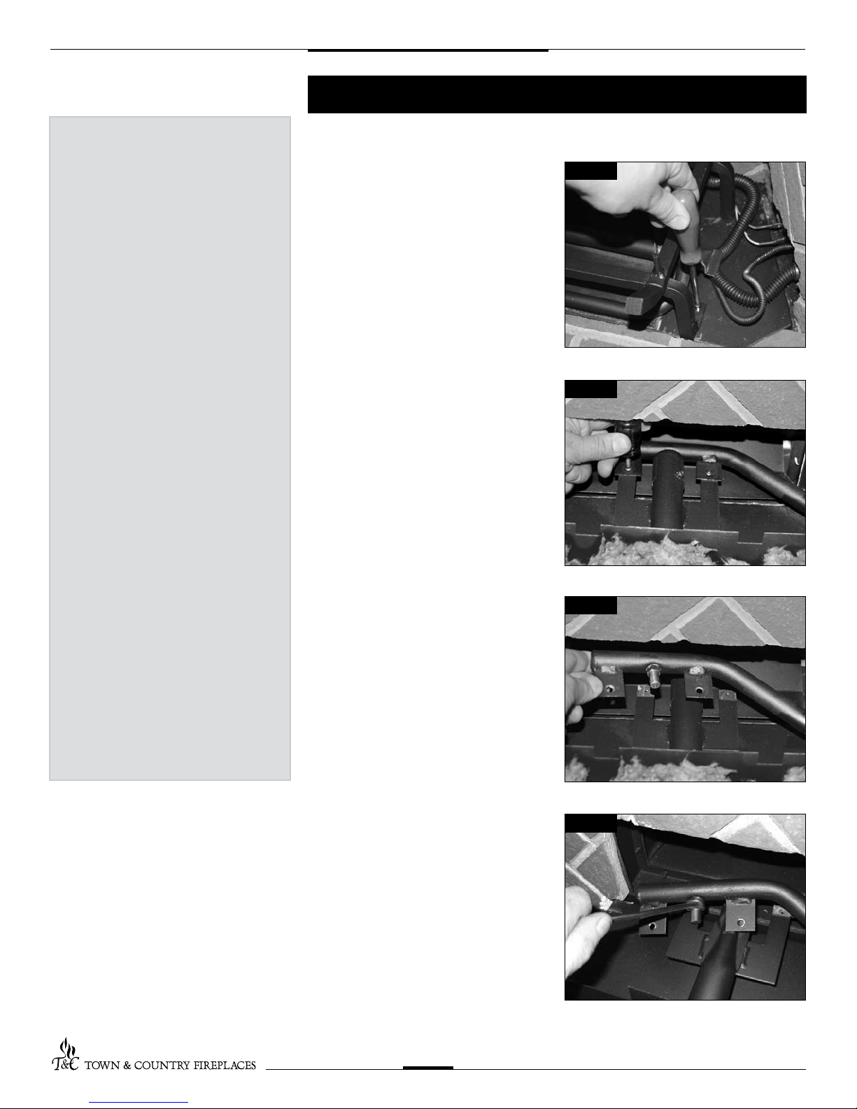
1. Attach the burner assembly to the oor of
the rebox with two screws. (Fig. # 1).
2. Attach the manifold supply tube to the
bulk head tting and tighten. (Fig. # 2)
Ensure that there are no leaks.
NOTE: Primary air shutter must
be fully closed for Natural gas or
fully open for Propane.
BURNER ASSEMBLY
EMBER MATERIAL
7 PCS LOG SET
HARDWARE PACKAGE
LOG GRATE
Fig #1
Fig #2
AIR SHUTTER
3
TC30.NG01.C 140708
Contents of Package
Burner/Grate Installation

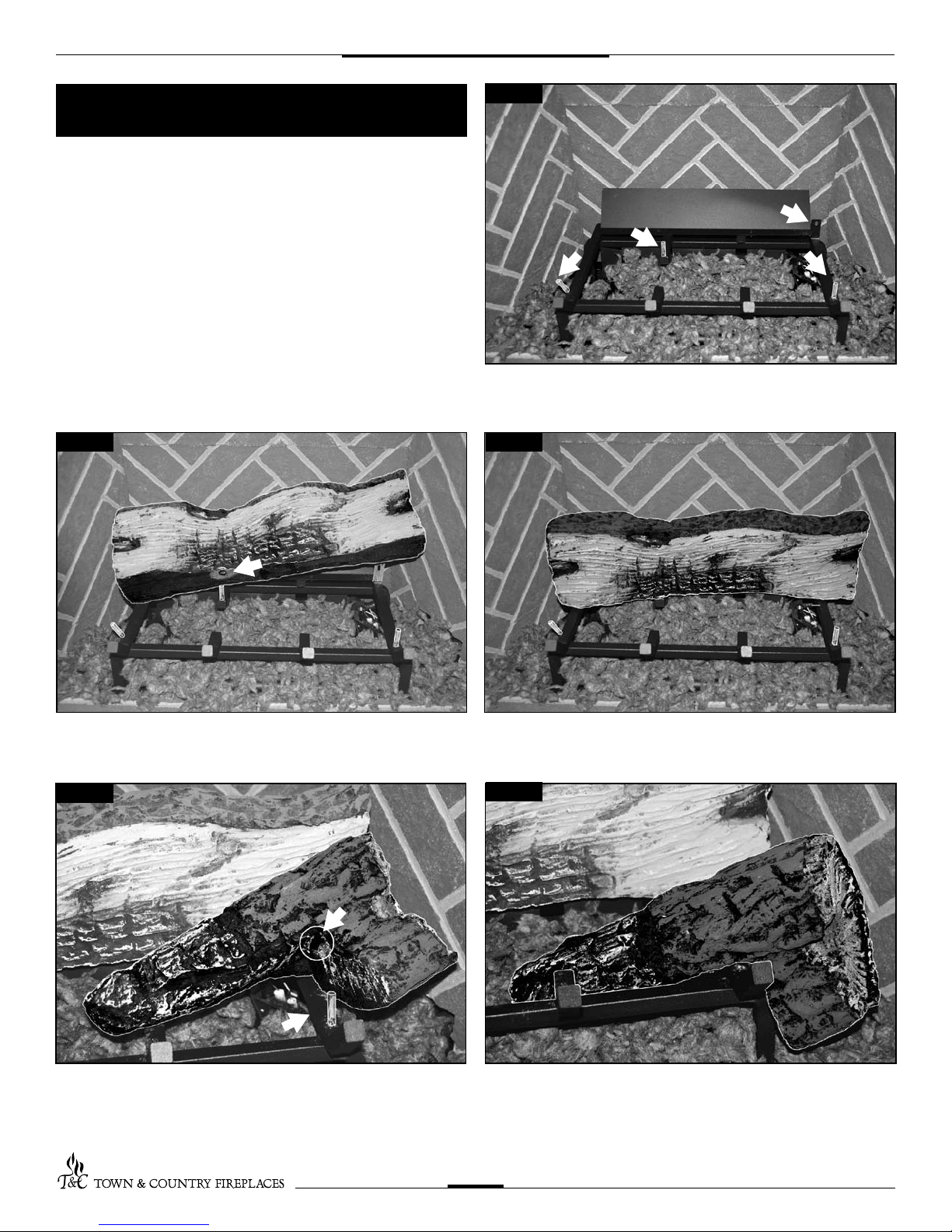
5. Position the grate over the burner tray
and attach to the oor with two screws
through holes located behind the front
legs of the grate.
(Fig. # 5)
6. Attach air deector to rear of grate with
two screws (Fig. # 6)
3. Attach the pilot supply tube to the bulk
head tting and tighten. (Fig. # 3)
Ensure there are no leaks.
4. Connect spark electrode wire
(ORANGE) to the rear electrical bulk
head tting. Connect the ame sensor
wire to the front electrical bulk head
tting. (Fig. # 4)
If appliance is to used with
propane gas see propane
conversion instructions on page
#6 before proceeding.
Fig #3
Fig #4
Fig #5
Fig #6
4
TC30.NG01.C 140708
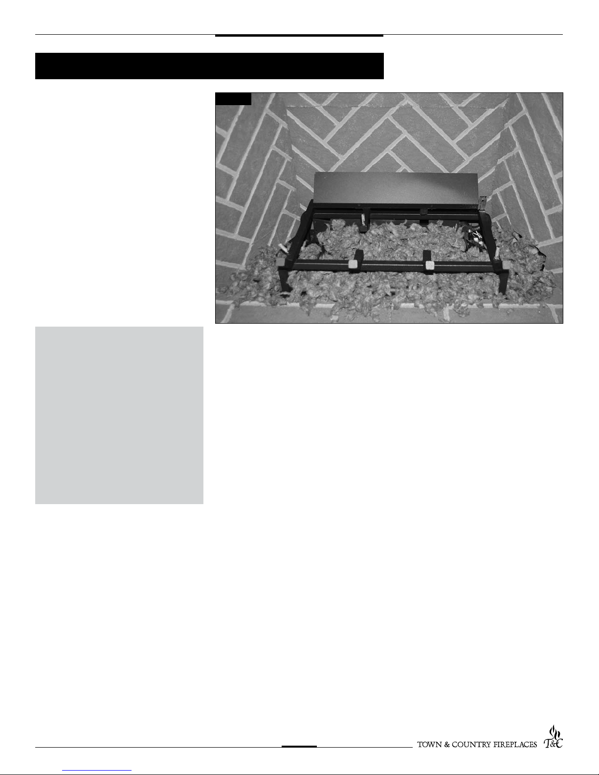
A large bag of ember material is shipped
with the replace and needs to be installed
to ensure optimum performance and ame
appearance.
1. Pull apart the material into ember size
pieces (approximately 1” squares) and
gently place them into the burner pan.
Do not compress, leave them loose for
best performance.
2. Fill the burner pan with embers until
level with the top of the pan at rear, and
gradually slope forward to the rebox
oor at the front, covering both burner
tubes.
3. Place remaining ember material outside
of the burner pan as desired to cover-up
gas lines and brackets.
Note:
Ember material placement and
amount will affect ame
appearance.
More ember material results in
lower ame height.
Add or remove as needed until
desired ame affect is achieved.
Reduce the amount used on
Propane models, as too much will
create soot.
Fig #7
5
TC30.NG01.C 140708
Ember Material
BASE LOG #1
PIN HOLE
PIN HOLE
PINS
TOP RIGHT LOG #2
PIN
STOP TAB
Fig #8
Fig #9 Fig #10
Fig #11 Fig #12
The logs are packaged in a foam pack inside the box. They are
fragile and should be handled with care. Unpack and inspect log
set. There should be a total of 7 logs. Gas plumbing and vent con-
nections should be completed before proceeding.
Position the logs as indicated by the following pictures. The three
main logs have holes and /or pins. Engage each pin in the cor-
responding holes. The remaining logs do not have holes or pins.
They rest in position. Locate as per the diagrams.
(Figs. #8 – #18)
6
TC30.NG01.C 140708
Log Set Assembly
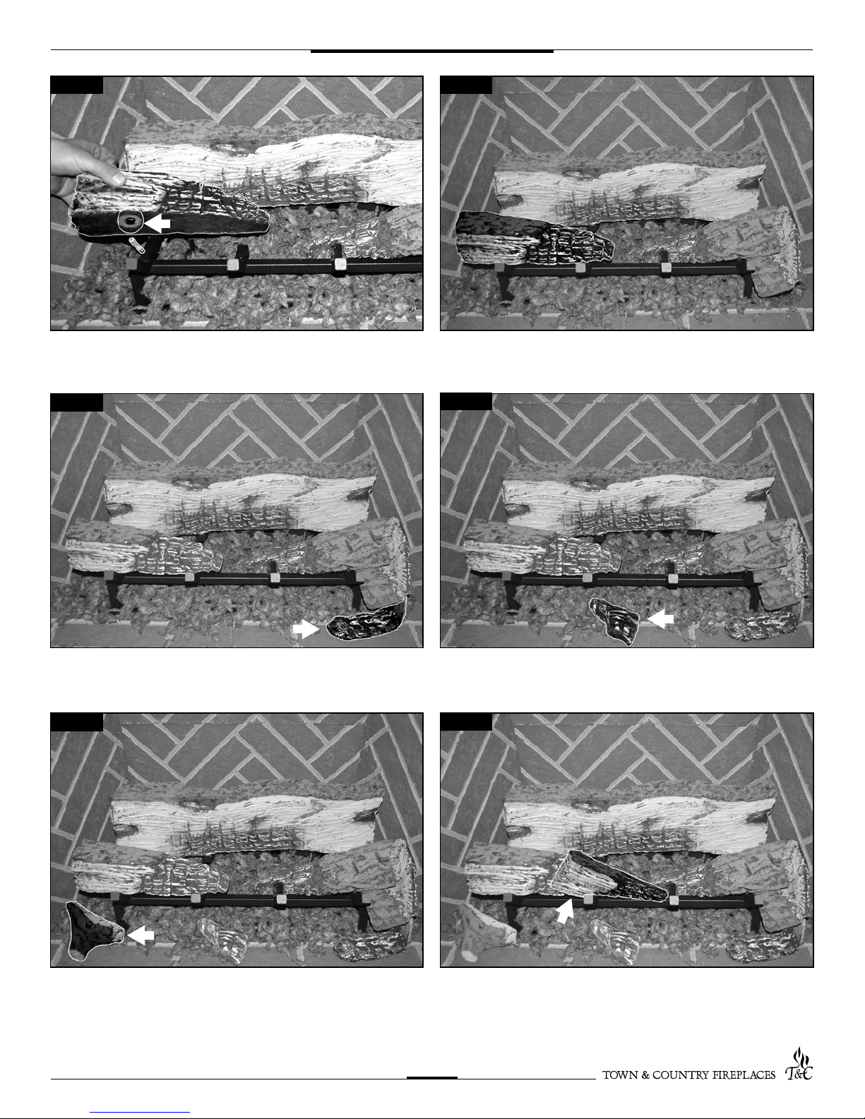
PIN HOLE
TOP LEFT LOG #3
BOTTOM RHS CHUNK #4 BOTTOM CENTER CHUNK #5
BOTTOM LHS CHUNK #6 CENTER CHUNK #7
Fig #13
Fig #15
Fig #14
Fig #16
Fig #17 Fig #18
7
TC30.NG01.C 140708
If the unit is to be used on propane
convert as follows using the
components supplied with this
burner:
CAUTION
The gas supply and electrical power
shall be shut off before proceeding
with the conversion.
Note: Factory supplied components must be
used to ensure correct input.
After conversion conrm proper manifold
pressure.
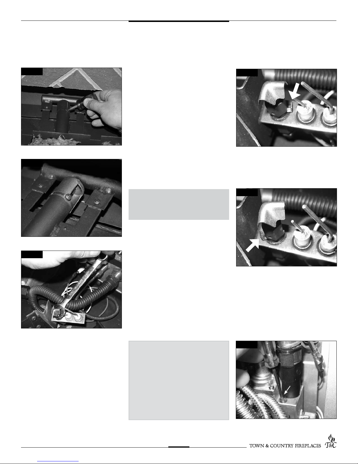
1. Ensure the burner, pilot and gas
supply are turned off, and the
appliance has cooled.
2. Remove the two screws securing the
the burner grate.
(Fig. #19)
3. Remove the two screws securing the
manifold assembly to the burner.
(Fig. #20)
4. Remove the manifold assembly from the
burner. (Fig. #21)
5. With a ½”wrench remove the natural gas
orice (#32) and replace with propane
orice (#48)(our part # 5021.3407)
(Fig. #22)
WARNING
This conversion kit
shall be installed by a
qualied service agency
in accordance with the
manufacturer's instructions
and all applicable codes
and requirements of
the authority having
jurisdiction.
If the information in these
instructions is not followed
exactly, a re, explosion
or production of carbon
monoxide may result
causing property damage,
personal injury or loss of
life.
The qualied service
agency is responsible for
the proper installation of
this kit.
The installation is not
proper and complete
until the operation of the
converted appliance is
checked as specied in the
manufacturer's instructions
supplied with the kit.
Fig #19
Fig #20
Fig #21
Fig #22
8
TC30.NG01.C 140708
Propane Conversion
The minimum rate screw is sealed with
an o-ring.Use a thin bladed screwdriver
to back the screw out to the limit of the
threads.
A groove on the screw body will be
visibe just above the valve body.Insert a
thin tool (knife blade or thin screwdriver
blade) into the groove and gently pry
the screw up.
Fig #25
Fig #26
Minimum
rate screw
6. Fully open the primary air shutter.
7. Reinstall the manifold and air deector
8. Witha7/16”wrenchloosenthe pilothead
on the pilot assembly by a half-turn
(Fig. #25)
9. Slide the pilot adjustment band over and
ensure that the hole in the orice band is
showing. (Fig. #26 shows NG position,
Fig. # 27 shows LP position)
Retighten pilot head.
10. Remove right hand brick panel (if
installed) and access panel located on
right hand side of rebox
(See Fig. #27).
11. Remove the minimum rate screw located
in the valve.
(Fig. #32)
NOTE: Primary air shutter must
be fully closed for Natural gas or
fully open for Propane.
Fig #23
Fig #24
Fig #27
Fig #28
9
TC30.NG01.C 140708
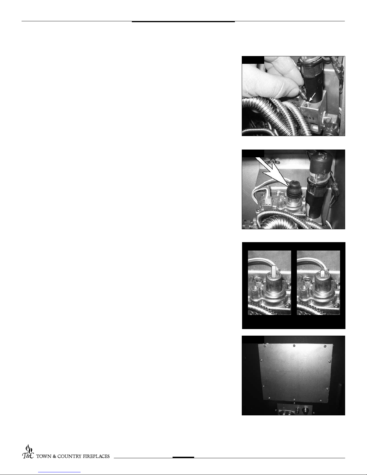
12. Replacetheminimumratescrewwiththe
one provided in the propane conversion
kit supplied with this replace. Ensure
that the screw is fully installed.
(Fig. #29)
13. Pull off the rubber cap from the top of
the pressure regulator. (Fig. #30)
14. Press down on the center post and
rotate 90°. The center post should
stay down. (Fig. #31). Replace the
rubber cap.
15. Fill in the date and the name of the
person who performed the conversion in
the white area on the conversion label.
Peel off the protective backing and apply
the conversion label directly over the
gas specications on the rating label.
16. Attach the access panel to the side of
the rebox with the previously removed
screws. (Fig. #32)
Note:
Gasket must be installed with access
panel.
Minimum
rate screw
NG LP
Fig #29
Fig #30
Fig #31
Fig #32
10
TC30.NG01.C 140708
Other manuals for TC30
1
This manual suits for next models
1
Table of contents
Popular Fireplace Accessories manuals by other brands


Bronpi
Bronpi KIT-1 instructions

Town & Country Fireplaces
Town & Country Fireplaces 22150051 instructions

Travis Industries
Travis Industries 33 DVI installation instructions

Superior
Superior ASD3628-TI installation instructions

pleasant hearth
pleasant hearth OFP28WG operating manual

IHP
IHP Astria Series manual

Firegear
Firegear FG-H-2110SS Installation and operating instructions

Nibe
Nibe Contura C i31 Installation instruction

kozy heat
kozy heat KZK-052 manual

SimpliFire
SimpliFire SF-WM36 Service manual

Bluegrass Living
Bluegrass Living BC18NR OWNER'S OPERATION AND INSTALLATION MANUAL

pleasant hearth
pleasant hearth IRIS SCROLL quick start guide