Sun Power XP Series User manual

V07-2014 Page 1of 24 ©
Australian made XP Series Automatic Gate Operators
Smart & Green Auto Gate Operators
Installation Guide & Owner’s Manual
Please DO NOT attempt installation
without reading &then following this manual
Take your time - Read the Manual - Get it right – Enjoy the benefits
Technical support is available if, after having read these instructions, you require assistance
This Instruction Booklet/Owner’s Manual, should be retained by Gate owner for future reference.
Further copies are available on our web site
Sun-Power Auto Gates
129 Gladstone Street, Fyshwick ACT 2609
Ph: 02-6280 4655 02-6280 4783 Fax: 02-6280 7592
email.sungate@bigpond.net.au www.sungateaustralia.net
This Manual is available on the website
Save Power
with
Sun-Power

V07-2014 Page 2of 24 ©
Contents:
Dear Installer/Owner 3 - 4
Introduction 3 - 4
Warning re wiring changes 4
Installation
Standard Installation 5
Install Radio receiver & Antenna 6
When to connect POWER 9
Installation Procedure 5 - 10
Adjusting Limit Switches 10
Side Mount Installation 10 - 11
Restricted side room 11 - 12
Out-swing Installation 12
Pre-wiring plus Control Board & Settings:
Auto Close, Multi-user 13
Overloads - Settings 13
Trim pots - Settings 14
Circuit board diagrams 15 - 16
L.E.D Sequence 17
Anti-clash leaf delay 18
SOLAR wiring detail 19
Options:
Push Button [PB] 17
Electric Lock [EL] 19
Photoelectric Safety [PE], Antenna 20
Troubleshooting/Radio Receiver/Transmitters
Trouble Shooting 20
Radio Receiver [Rx] 20 - 22
Radio Transmitters [Tx] 20 - 22
Antenna [Ant] 20 - 22
Programming Radio Transmitters 23
Specifications/Freight Dimensions 24
Sun -Power Auto Gates reserves the right to make upgrades & alterations without notice

V07-2014 Page 3of 24 ©
Dear Installer/Owner
Your Australian Made SUN-POWER XP Series Auto Gate Operator has been designed and
built to make installation simple and maintenance almost Non - existent.
To save you time, and make installation easier, The Circuit Board is pre-wired & placed under the
powder coated, steel weatherproof cover together with the Motor/Gears/Battery, this means that
you do not have to spend extra time wiring up to a separate control box. The Radio receiver,
3 Remote Controls & 2 Key pads [Keypads in Deluxe Kits only] are pre-programmed. Circuitry for
most options is already included. You simply have to connect up the external devices such as Radio
Receiver, Solar Panel, Antenna, Push buttons etc.
The design features, in the SUN-POWER XP Series Gate Operators, will save you time on site, and
the installation will be neat & tidy.
Apart from its physical attributes the control circuit has some powerful operating features. These
can be adjusted on site, without modification to suit a range of situations.
This Manual should answer most of your questions regarding the installation and operation of the
SUN-POWER XP Gate Operator. If further information is required, please email, fax, phone or
write to us.
Note:
Primary [Master] Operator has a Circuit Board and can be installed on LH or RH]
Secondary [Slave] Operator does NOT have circuit board, can also be mounted on LH or RH
Introduction:
The SUN-POWER XP Series INTELLIGENT Automatic Gate Operator is an electronically controlled
Automatic Gate Operator for swing gates. A range of features are built in to the XP and a range of
options is also available.
The Sun-Power XP Series Operators can be used in a variety of situations.
240V AC • SOLAR Power • 12V AC/DC
Single Gate or Pair of Gates • Normal or Restricted side-room applications
Where a Gate is require to swing beyond 90° and up to 130° [Or less than 90º]
A powerful control system gives the flexibility to change some important characteristics of the
operation. Including …………..
Automatic close • Signal to close • Sensitivity to obstacles • Multi-user
function
The control system also allows for the addition of the following options.
• Digital Keypads • Push Buttons • Photoelectric cells • Security Systems
• Electric Locks etc
For all its sophistication the Sun-Power XP Series Auto Gate Operator is extremely reliable and its’
rugged construction ensures a long trouble free life.
Take your time - Read the Manual – Get it right – Enjoy the benefits

V07-2014 Page 4of 24 ©
This SUN-POWER XP Auto gate Operator has undergone rigorous factory load testing and has been passed
as ready for site installation.
Please ensure that you read ALL of these instructions, plus any other instructions supplied, then simply
follow Instructions step by step.
Power - 240V/12V/Solar Panel/Battery must not be connected until appropriate [see item 6 page 9].
IMPORTANT: Do NOT alter any pre-wiring of circuit board [except motor polarity* when necessary].
Altering Pre-wiring [except motor polarity*] will compromise your warranty
* ALL power [240v/12V/Solar/battery] must be disconnected before attempting to change motor
polarity
XP Series Swing Gate Operators are suitable for and guaranteed when the gates [up to 300 kg*] are
correctly hinged and operate smoothly and evenly.
*XP Series Gate operators will drive a variety of Gate Styles, Sizes & Weights. Suitability is dependent on
the quality of hinging and the force required at One Metre from the hinge center-point to open and close
the gate, 15 Kg is the maximum for gates opening IN [PULL] and 7.5 Kg for gates opening OUT [PUSH]
If you do not understand any of the instructions, or have any doubts, then please Fax 02 6280 7592 or
Email your queries [email protected] or ring us on 02 6280 4655 re your concerns before you apply
power to the unit or you may void your warranty
DO NOT connect the RED Spade Terminal to the Battery until you are ready to set the Limit Switches. The
RED Spade Terminal is supplied, disabled* from the Battery. [* i.e. Not connected to the Battery]
The last item to be connected is the SOLAR PANEL, do this after ALL other settings and adjustments have
been made.
Important: [Battery change - Circuit board posts - Motor polarity change - Photoelectric Safety]
Before moving the circuit board for any reason [or changing motor polarity], including when changing the
Battery, you must ensure that ALL Power from any 240v/12V/ Battery/ Solar Panel is disconnected to
avoid damage to the circuit board. The Circuit board is supplied mounted on top of 4 nylon ‘posts’ in this
position they act as spacers, ensure these ‘posts’ remain in place and circuit board is correctly located on
top of these posts. There is a copper wire [a ‘bridge’] connecting the PE terminals, DO NOT REMOVE this
‘bridge’ unless connecting photoelectric safety cells or unless otherwise instructed.
Ensure that there are NO loose wire strands when disconnecting and connecting any wires.
Do not expose control board or any electronic circuitry to any …… • Lubricants • Moisture • Rain
• Insecticide spray or any ‘foreign’ materials
No cabling must be run in conjunction with any high voltage cables or electric fencing – if in doubt, seek
advice from a qualified Electrician in Your State or Territory.
Installation:
Standard Installation. [PULL]
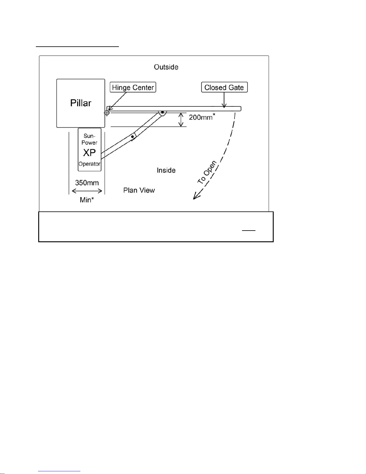
A “Standard Installation” is one where gate[s] open in. [swinging INWARD toward the Motor Housing].
Generally the gate hinge should be no more than 200mm from the rear of the Pier/Post/Pillar, ask us for
advice if this distance is greater.
Side room of 350mm is normally required to accommodate the swing of the arms.
Refer to Pages 13 & 14 if there is restricted side room [See fig 1] some pictures of restricted side-room
installation are in the “image gallery at “ www.sungateaustralia.net
©

V07-2014 Page 5of 24 ©
Installation procedure:
Refer page 10 if restricted side room
1.
Ensure that the gates swing freely and that all existing latches/padbolts/Chains etc are disabled or
removed from the gate & Gate posts
2.
When using a 240v Unit [XP 100 or XP 100/300] the Master operator [the one containing the
Circuit Board] should be fitted to the Gate Post nearest the Power Supply.
Remove the cover, from the XP Operator [taking care that you DO NOT expose circuit board
to any moisture] to access the slotted fixing holes cut in the rear of the Chassis. Bend the
tabs out and bend them back against the rear of the chassis, in this position they act a
spacers allowing clearance for the cover[s] NOTE: [Do not remove these tabs – just bend
them out and fold them to the back] [Unless you are using the optional XP-MP Mounting
Plate]
3.
Position each unit on the gate post/pier/pillar[s]
The vertical position is found by locating the gate bracket. The Gate bracket is best placed where
there is adequate fixing on the gate and movement of the arms is unrestricted [See Fig. 2]
The XP Auto Gate Operator[s] may now be bolted in place.
Fig 1. Standard Installation:
*Where the distance is greater than 200mm the Secondary arm may
need to be extended, contact Sun-Power if you need assistance.

V07-2014 Page 6of 24 ©
INSTALLING THE RADIO RECEIVER:
Step 1. Ensure that Positive lead [RED] is disconnected and away from the
Battery Positive terminal
Step 2. Ensure Solar Panel [or Mains power] is NOT Connected to the Gate
operator
Step 3. Line up the ports on the radio receiver [Rx] with the 6 PRONGS on the
Main circuit board - now slide the Radio Receiver [Rx] fully onto the 6
prongs at the bottom end of the main circuit board.
Attaching the Antenna.
Step 1. Attach the end of the Antenna cable to the Radio receiver board
[When ready]
Attach Radio receiver board Attach Antenna
Note: Kits from February 2014 come with a Box marked Rx30M this contains
3 Remote Controls [Tx10], 2 Keypads [DK50] and 1 Radio receiver [Rx 30].
The Remotes and Keypads are pre-programmed to the radio receiver.
Refer to page 19 for further information on Remotes and Keypads etc

V07-2014 Page 7of 24 ©
4. If you have a Pair of Gates then……….
Connect the Slave to the Master Unit with 2 Core Flex-Cable [Max load draw 8 Amp at 12
Volts]
[Fig.8 cable - .75mm sq – 24/.020 minimum] Refer Fig. 3
All cabling must not be run in conjunction with any high voltage cables or electric fencing – if in doubt,
seek advice from a qualified Electrician in Your State or Territory.

V07-2014 Page 8of 24 ©
©
The XP Operators are set in the factory for a “Standard PULL Installation” When the Master
Operator is placed on the LEFT HAND SIDE [from the inside [motor side] – looking out] the wiring
is Brown above Blue [ref. P. 15 - 16]
When the Master Operator is located on the RIGHT HAND SIDE [motor side - from the inside–
looking out] then the motor wires need to be reversed. ie; BLUE above BROWN.
To accomplish this, locate the connection blocks for each motor on the Circuit board.
Swap*the BROWN &BLUE wires for Motor 1 [& Motor 2 if a pair of gates] [See Figure 3
above].
IMPORTANT:
*ALL power including • 240v • 12V • Solar • Battery must be disconnected
before attempting to change motor polarity
5.
Location of Gate Bracket on Gate:
The Gate bracket should be positioned on the gate so that the arms are ALMOST in a
straight line when the gates are closed [Ref. P.9 Fig. 4] To check the location of the gate
brackets, first disengage the Main arm from the drive shaft [Using the spanner provided,
unscrew the bolt until the arm swings freely] Then clamp the gate bracket in position. Open
and close the gate to ensure the gate bracket is appropriately located.

V07-2014 Page 9of 24 ©
©
6. Connect power [12v or 240v or Solar] to the Master Operator and connect the Battery
7. The Limit Switches may now be adjusted [If necessary] [See figure 5.] Each of the Master and
Slave Operators has its own pair of cams, one to set the open position & one to set the closed
position.
Firstly mark the position of each cam as a reference. Loosen the screw holding the Cams.
NOW you can drive the XP Operator with the transmitter & NOTE which cam controls the opening
and which cam operates in the closing motion. [The Cam activates a Limit Switch to turn off the
Motor]
Re-position each Cam and operate the XP again. Repeat until the Gates open & close to the
required positions.
©

V07-2014 Page 10 of 24 ©
Side Mount Installation:
The XP Operator may be mounted sideways, with the long side against the Pier/Post, for extra
flexibility.
This feature is very useful for situations where … [Ref. P 10. Fig. 6]
The Gate must swing further than 90 degrees
The Gate swings outward.
The Gate swing outward & it is positioned at least 400mm forward of the back of the
Pier/Post
Note: See also section on Out-swing Installation.
©
When side mounting, each XP Operator should be fitted to the Pier/Post with its output shaft close
to the gate hinge. With this in mind the “Standard Installation” instructions may now be followed.
Optional Side Mount cover sets with backing plate[s] are available, and must be used for
SIDE MOUNT installation.
Restricted/Limited Side Room Installation:
This term is applied to the situation where the movement of the Standard Arms cannot be
accommodated within the side room available. [www.sungateaustralia.net ] Images Gallery show a
typical limited side room installation.
In most situations this problem can be overcome by cutting down the secondary arm [The link
joining the Gate to the Primary arm].
This new length can be approximated by the following procedure.
i. Move the Primary Arm to a position suitable for the closed gate.
Remembering that in the closed position the Primary & Secondary arms must stop short
of a straight line alignment [See figure 7]
Other manuals for XP Series
1
Table of contents
Other Sun Power Gate Opener manuals