Steltronic Stand Alone Vision Lane Computer User manual

1
Steltronic Stand Alone Vision lane computer installation (rev c.)
Stand Alone Vision Lane computer
Installation manual (rev c.)
Worldwide Headquarters
Steltronic S.p.A.
Via Artigianale 34, 25082 Botticino Sera Brescia - Italy
Tel: +39 030 2190811 fax: +39 030 2190798
http://www.steltronic.com
Worldwide Service: + 39 030 2190830
Email: service@steltronic.com
North America Headquarters
Steltronic Incorporated
2738 S. 163rd Street
New Berlin, WI. 53151
Toll Free: (800) 942-5939
Telephone: +1 (262) 754-2300
FAX: +1 (262) 754-2301

2
Steltronic Stand Alone Vision lane computer installation (rev c.)
Index
Warnings ........................................................................................................................................................................... 3
General.............................................................................................................................................................................. 4
General installation note ..................................................................................................................................................5
Stand Alone VLC connection diagrams .............................................................................................................................6
VLC (Vision Lane Computer) connection view ..................................................................................................................8
API Lane Computer & Bowlers Console- “Long Cable” installation ..............................................................................9
Lane Computer Pinsetters “Long Cables” installation without API ............................................................................10
Steltronic cables diagrams ..............................................................................................................................................11
Stand Alone VLC software settings .................................................................................................................................15
Access to the Stand Alone configurator (from QWERTY bowler’s Console)...................................................................20
Access to the Stand Alone configurator (from Steltronic Bowler’s Console emulator) .................................................20
Access to the Stand Alone configurator (from local keyboard and mouse) ...................................................................22
Access to the Stand Alone configurator (using Remote Desktop or VNC from a laptop)...............................................22
Stand Alone configurator................................................................................................................................................23
Ticket dispenser configurator .........................................................................................................................................24
Pinsetter Configurator ....................................................................................................................................................25
Setup the Stand Alone Vision settings (using a Temporary Focus Front Desk) ..............................................................28
About PinDetect Calibrator.............................................................................................................................................31
Pin detect calibrator (Sciba)............................................................................................................................................32
Pin detect calibrator (PinCam)........................................................................................................................................36
Commit the VLC HD.........................................................................................................................................................39

3
Steltronic Stand Alone Vision lane computer installation (rev c.)
Warnings
This manual contains instructions for the installation of Stand Alone VLC only.
Please contact Steltronic service for pinsetter interfacing, Camera installation and any other installation or user
manuals that could be necessary.
Steltronic Stand Alone VLC is a Lane Computer that needs custom configuration files,
please, contact Steltronic service to obtain the VLC setup in the proper way; in the request form
please specify the pinsetter model to interface.
Any attempt of hard drive cloning or mother board replacing will cause configuration key corruptions
and the unavailability of VLC, please contact Steltronic Service in case of hardware problems.
A Bowler’s Console is mandatory for access to the bowler’s menu options.
The VLC Stand Alone configurator menu is accessible only from Bowler’s Console equipped with wired QWERTY or
ABC keyboard; in installation with Joystick (wired or wireless)\Touch Screen bowler’s console, the installer need a
keyboard + mouse connected to the VLC, in order to access to Stand Alone configurator menu, otherwise a laptop
equipped with at least one of the following program:
VNC Viewer
Steltronic Bowler’s Console emulator
Steltronic Focus Front Desk software (min. plug in required, lane manager\lane server)
The Vision software version referred to this manual is 12.18
For further information or request, please contact service@steltronic.com

4
Steltronic Stand Alone Vision lane computer installation (rev c.)
General
The VLC (or V.L.C.) is the acronym name for Vision Lane Computer. The Stand Alone VLC is a special lane computer
for Scoring System, designed to be installed in small entertainment centre, pub, hotels, on any place where is not
necessary the use of the Front Desk functions. To open the lanes and play, the players insert token\money in the
coin\money boxes, (usually located near the bowler’s console), alternatively the cashier can turn on a “toggle
switch” that remain closes until player end to play.
Each Stand Alone VLC could be used for equipped one lane or one pair of lanes. Pinsetter Interfacing, long and
short cable are the same of a VLC installation with Focus Front Desk, the bowler’s console is mandatory for operate.
VLC could be interfaced with vary pinsetters (see the following list), the * means “NO Camera required for pins
detection”, the ** means “NO Pinsetter interface (A.P.I.) required”.
AMF 8270 -solid state chassis (5 boards\Omnimboard)
AMF 8270 µP Chassis (with APS)- VPS 2000/3000
AMF 8230/8245/823000
AMF 8290 “Big Chassis”
AMF 8290-XL - AMF with ZOT 8290-XL chassis
AMF-Qubica 8290 Xli – AMF with ZOT 8290 Xli chassis
Brunswick A1/A2
Brunswick (Schmid )GS10 Red chassis
*Brunswick GS92/96/98
*Brunswick GS-X NexGen
* Brunswick Eclipse (String p.)
*Brunswick Convertible 5-10 pins (String p.)
*Schmid PBS81-5 (String 5 pins)
*Vollmer 10 CPU KS-34C (String p.)
**Kebo-tech (Vollmer) Vision-3 chassis (String p.)
* Schmid K-740E (String p.)
*Spellman (String p.)
*Vilati – chassis K-800-E (String p.)
Yangji Vision
*S.E.S. 2003 (String p.)
**S.E.S. 2012 (string p.)
Via Bowling MC2 – Via B. MC2 with Switch chassis
**Via Mini-bowling
Funk KF3000
*Mendes 500 Mechanic
Mendes- Mag3
The bowler’s console model recommended for Stand Alone VLC is UFO QWERTY (single or double), anyhow the
Stand Alone VLC could works with Joystick (wired or Wireless) or Touch screen bowler’s console monitors. When the
installation is made with joystick or touch screen bowler’s console, the installer must be equipped with keyboard +
mouse or laptop with VNC Viewer and\or Steltronic Bowler’s Console emulator and\or Focus front desk program.

5
Steltronic Stand Alone Vision lane computer installation (rev c.)
General installation note
The VLC must be placed in a safe and clean place. Usually there are two possible locations for VLC:
a) Near\behind the overhead monitors (the max clearance from the monitors depends by VGA cables, usually
1,8 meters)
b) Pinsetter area, generally on the curtain wall, near to API or pinsetter chassis.
Electrical requirements
Installation (a): Is required #1 receptacle with 3 outlets for each of pair of monitors lanes. Place the receptacle
(flush mounted on the ceiling) as close as possible to the location of where the monitors will be placed,
considering that each monitor is supplied with a power cord of 1,8 meter length (5.9 feet). A circuit breakers
located in a new electrical panel, accessible by bowling staff, should control each pair of monitor (max 4
monitors, depends by circuit breaker model).
Installation (b): each lane computer should be located on the curtain wall, close to the Steltronic A.P.I. or
pinsetter chassis, considering that the CA0092C cable from API to VLC is 80 cm-31.4”.
Is required #1 duplex receptacle with 1 outlets for each lane computer; place the receptacle close as possible to the
Lane computer, considering that each lane computer is supplied with a power cord of 1,8 meter length. A circuit
breakers located in a new electrical panel, accessible by bowling staff, should control each lane computer (max 3
VLC, depends by circuit breaker model).
Is required #1 duplex receptacle with 2 outlets for each of pair of monitors lanes. Place the receptacle (flush
mounted on the ceiling) as close as possible to the location of where the monitors will be placed, considering
that each monitor is supplied with a power cord of 1,8 meter length (5.9 feet). A circuit breakers located in a new
electrical panel, accessible by bowling staff, should control each pair of monitor (max 4 monitors, depends by
circuit breaker model).
The video signal from VLC to the overhead monitors could be provide with CAT video system* or using a H.Q. Long
VGA cables (one for each monitor).
Long cables, Pinsetter interface and bowler’s Console installation for Stand Alone VLC are the same of Standard
VLC installation, proceed in the same way.
Coin/money drop box and cables are not supplied by Steltronic Spa, please contact your score vendor for further
details.
* see the CAT video installation manual for further details.

6
Steltronic Stand Alone Vision lane computer installation (rev c.)
Stand Alone VLC connection diagrams
Installation with A.P.I. (Advanced Pinsetter Interface)
Installation without A.P.I.(pinsetters connected to VLC via RS232)

7
Steltronic Stand Alone Vision lane computer installation (rev c.)
Some of the devices indicated in the diagrams are optional and depends by the center configuration and customer
request, anyhow the following items are strictly necessary for one pair of lane’s installation:
#01 Stand Alone VLC (Vision Lane Computer)
#01 power cord for VLC
#01 DVI adapter (supplied with VLC)
#01 Bowlers console (+ interfacing cables set)
The following items depends by the installation method and pinsetters models (list is for pair of lanes):
VLC installed near or behind the overhead monitors:
#02VGA SubD15 male-male high quality cable (min. length 1,8 Mt)
VLC installed in the pinsetter area:
#02 H.Q. VGA long cables or #01 CAT video system (Cat video system consist in #02 Rx devices, #01 TX
device,# 04 VGA SubD15 male-male high quality cable, #01 CA0315 splitter cable for each pair of lanes)
Installation with API (Advanced Pinsetter Interface):
#01 CA0092A/CA0092B/CA0092C cable (RS232+12VDC cable, from Lane computer to A.P.I.), the CA0092C is
used when the VLC is installed close to the API.
#04 wires cable for coin input (lay the cable from API to coin devices, 2 wires each side)
#01 API – Advanced Pinsetter Interface
#01 Camera for pins detection(if required for detecting pins) + cables for connections
#02 Short cable kit for pinsetter Interfacing
#02 Coin drop box or toggle switch (not supplied by Steltronic Spa)
Installation without API (pinsetters connected to VLC com’s):
#02 Coin Cables adapter
#02 Coin drop box or toggle switch (not supplied by Steltronic Spa)
#02 RS232 cable (from VLC com’s to Pinsetter chassis, models depends by pinsetter type)
Additional cable for installation with PinCam (camera for detect knocked pins):
#01 standard UTP network cable (CAT5\CATe\CAT6) need to lay from the PinCam to the corresponding VLC.
this “Stand Alone Network connection” is mandatory to perform the camera calibration from Stand Alone
Menu; is also mandatory install the antistatic discharge line between the devices
see PinCam installation
manual for further details.

8
Steltronic Stand Alone Vision lane computer installation (rev c.)
VLC (Vision Lane Computer) connection view
Installation with PinCam (camera for pins detection): connect the UTP cable from each PinCam to the correspondent
VLC,, using the LAN input.
VLC monitors output
The VLC monitor output is Analog video, XGA, 1024 x 768 pixel. Is possible connect #01 monitor for each lane of
the lane pair or #01 monitor\projector for both lanes of the same pair. The monitors must be powered directly from
AC outlet; monitor Stand-by and Input switch Score/TV can be perform as following: a)with monitor remote control
b) via VLC: with monitors compatible with Steltronic software, the VLC could send a command (via RS232) to switch
the monitor in Stand-by/TV/AV/SVideo, when the lane is not in use.
Contact service@steltronic.com for the list of compatible “RS232 commands” monitors model.
The VLC send only the Score signal to the monitors, AV/RF/SVideo signal must be connected directly to the
overhead monitor inputs; see the monitor installation manual for further details.
VLC AC Input
The VLC AC input power is 110AC/220AC/240AC; please check the VLC power supply model and switch before to
plug the VLC to the AC outlet.

9
Steltronic Stand Alone Vision lane computer installation (rev c.)
API Lane Computer & Bowlers Console- “Long Cable” installation
Example of Installation [A] where each Lane computer is installed behind the monitors.
CA0092 and the Network cable are routed into a conduit ( ≥Ø4 cm, 1.57 inch) laid above the ceiling tiles.
The CA0092 cable is available in two measures: CA0092A= length 33 meters (108.2 feet)
CA0092B= length 40 meters, maximum allowed(131.2 feet).
The network cable (standard UTP cat cable) must not exceed 80 meters; the network cable is used only for
installation with PinCam, is not necessary in installation with Sciba.
The bowlers console cable is routed into a conduit(≥ Ø4 cm, 1.57 inch), laid under the bowling lane tracked by side in
the bowler’s return channel.
Example of Installation [B] where each Lane computer is installed in pinsetters area, on curtain wall, monitors are
connected with CAT Video System or using High quality long VGA cables.
The Lane computer is mounted on the Curtain wall of Pinsetter area; the overhead monitors are connected with cat
Video cable to Lane computer or with a high quality long VGA cables; the connection with API is made with CA009C
cable which length is 1 meter (3.2 feet).
The network cable is used only for installation with PinCam, cable is not necessary in installation with Sciba.
The video wires are routed into a conduit ( ≥Ø4 cm, 1.57 inch) laid above the ceiling tiles (see the CAT Video system
manual for further details). The bowlers console cable is routed into a conduit( ≥Ø4 cm, 1.57 inch) laid under the
bowling lane, tracked by side in the bowler’s return channel.
Lane
Computer
Bowlers
Console
API
CA0092A or
CA0092B
cable
Bowlers Console
cable
Bowlers Console
cable
Bowlers
Console
Lane
Computer
API
CA0092C
cable
CAT Video Cables –
H.Q. VGA long cables
Overhead
Monitors
Overhead
Monitors
PinCam
Cat 5
network
cable
PinCam
Cat 5
network
cable

10
Steltronic Stand Alone Vision lane computer installation (rev c.)
Lane Computer Pinsetters “Long Cables” installation without API
Example of Installation [A] where each Lane computer is installed behind the monitors.
the RS232 cables are routed into a conduit ( ≥Ø4 cm, 1.57”) laid above the ceiling tiles.
The bowlers console cable is routed into a conduit(≥Ø4 cm, 1.57”) laid under the bowling lane and it joint the
CA0359B cable in the pinsetter area.
Example of Installation [B] where each Lane computer is installed in pinsetters area, on curtain wall, monitors are
connected with CAT Video System or using High quality long VGA cables.
The Lane computer is mounted on the Curtain wall of Pinsetter area; the overhead monitors are connected with cat
Video cable to Lane computer or with a high quality long VGA cables. The video wires are routed into a conduit ( ≥Ø4
cm, 1.57”) laid above the ceiling tiles (see the CAT Video system manual for further details). The bowlers console
cable is routed into a conduit( ≥Ø4 cm, 1.57 ”) laid under the bowling lane, the cable is connected to the COM1 of
the Lane computer through the CA0359A cable adapter.
Lane
Computer
Bowlers
Console
Pinsetter
chassis
(Even
lane)
CA0359B
(console cable adapter
L= 30 meters)
Bowlers Console
cable
RS232
Even cable (L= 30 meters)
Pinsetter
chassis
(Odd lane)
Overhead
Monitors
RS232
Odd cable (L= 30 meters)
Bowlers Console
cable
CA0359A
(console cable adapter
L= 20 centimeters)
Lane
Computer
Bowlers
Console
Overhead
Monitors
Pinsetter
chassis
(Odd lane)
Pinsetter
chassis
(Even
lane)
RS232
Even cable (L= 3 meters)
RS232
Odd cable (L= 3 meters)
CAT video cables or high
quality VGA cables
Table of contents
Popular Computer Hardware manuals by other brands

EMC2
EMC2 VNX Series Hardware Information Guide

Panasonic
Panasonic DV0PM20105 Operation manual

Mitsubishi Electric
Mitsubishi Electric Q81BD-J61BT11 user manual

Gigabyte
Gigabyte B660M DS3H AX DDR4 user manual

Raidon
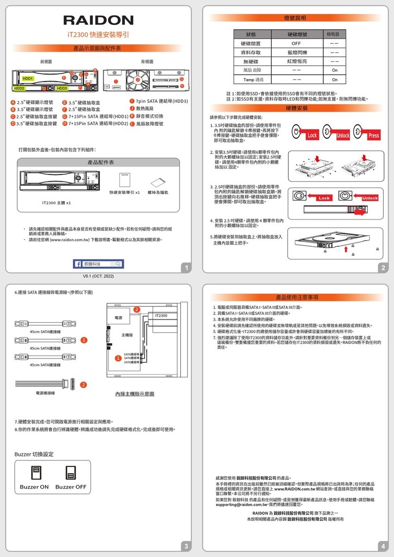
Raidon iT2300 Quick installation guide

National Instruments
National Instruments PXI-8186 user manual