SPYKER SPYDSB-9G User manual

Page 1©2021 Spyker Spreaders/A Brinly-Hardy Co. 1019622-C
SPYDSB-9G Drop-In Sprayer with 62” Boom
!!IMPORTANT
This manual contains information for the safety of persons and property.
Read it carefully before assembly and operation of the equipment!
OPERATOR'S MANUAL
Spyker Spreaders
Contact us at 800.972.6130
www.spyker.com

Page 2English Manual 1019622-C
Table of Contents + Safety
OPERATE SAFELY
Read Before Using:
Pesticides can cause personal injury and harm the envir-
onment when used improperly. Be sure to follow label
recommendations concerning safety and disposal.
SET-UP PROCEDURE
The SPYDSB-9G was pressure tested prior to shipment.
Some components were disassembled for packaging and
shipment. The basic set-up procedure is as follows:
• Remove the spray wand from inside the tank.
• Remove all contents from the box.
• Cut the plastic ties holding the boom sections together.
• Report any missing or damaged items to your dealer
immediately.
NOTE: The pink liquid residue in the tank is RV antifreeze.
Flush out the tank before use.
TABLE OF CONTENTS
Safety . . . . . . . . . . . . . . . . . . . . . . . . 2
Parts . . . . . . . . . . . . . . . . . . . . . . 3 - 8
Assembly . . . . . . . . . . . . . . . . . . 9 - 11
Use and Care
Operation & Maintenance . . . . . . 12
Initial Start-Up & Pressure . . . . . 12
Battery Recharging . . . . . . . . . . . 13
Spray Nozzle Settings . . . . . . . . . 13
Calibration . . . . . . . . . . . . . . . . . 14
Troubleshooting . . . . . . . . . . . . . 15
Accessories . . . . . . . . . . . . . . . . . 16
Warranty . . . . . . . . . . . . . . . . . . . . . 18
Observe all safety precautions including
wearing of protective clothing and equipment.
COMPATIBILITY
The SPYDSB-9G is designed to fit the
following spreaders:
SPYKER • S10 0 -12011
LESCO • 101186
• 105821
• HPS Chariot

Page 3English Manual 1019622-C
BATTERY AND SPRAY WAND
MOUNTING HARDWARE
SPRAYER HANDLE
WAND PARTS
Parts
DO NOT RETURN PRODUCT IF YOU ARE MISSING PARTS. PLEASE CALL: 1 (800) 972-6130
1
3
4
5
2
6
7
No. Part # Qty Description
1 1019634 1 Angle Bracket
2 1019635 2 Wing Nut
3 1019636 2 Mounting Clip
4 1019637 2 Screw #6 x 1/2"
5 1019638 2 Pan Head Screw
6 1019639 2 Fender Washer
7
1019640 2 Eye Bolt
1019641* 2 Eye Bolt *Optional Alternate (H.C. Battery)
8 1019691 1 Extension Wand
9 1019692 1 Trigger Jet Valve
10 1019693 1 Turbo TeeJet Nozzle Tip
11 1019694 1 Cap Nut
12 1019695 1 Angle Adapter
13 1019696 1 50 Mesh Screen
8
910 13
12
11

Page 4English Manual 1019622-C
Part Explosions
DO NOT RETURN PRODUCT IF YOU ARE MISSING PARTS. PLEASE CALL: 1 (800) 972-6130
ELECTRICAL
COMPONENTS
No. Part # Qty Description
14 1019642 1 Toggle Switch
15 1019643 1 Switch Bracket
16 1019644 1 Pump / Switch Wiring Assembly
17 1019645 1 Screw Clamp
18
1019646 1 Battery
1019647 1 Battery *High Capacity
19
1019648 1 Battery Wiring Assembly
1019649* 1 Battery Wiring Assembly *Optional H.C. Battery
20 1019650 1 Fuse Holder
N/A 1019651 1 20 Amp Fuse
14
16
17
15
19
16
18
20

Page 5English Manual 1019622-C
Part Explosions
DO NOT RETURN PRODUCT IF YOU ARE MISSING PARTS. PLEASE CALL: 1 (800) 972-6130
BOOM COMPONENTS
DIAGRAM
No. Part # Qty Description
21 1019697 1 Right Boom Section
22 1019698 2 Hose, 3/8" ID x 24"
23 1019699 2 Spring, Stainless Steel
24 1019700 1 Center Boom Section
25 1019701 1 Hose, 3/8" ID x 21"
26 1019661 1 Hose Barb Wing Nut Assy. 3/8"
27 1019702 1 Left Boom Section
28 1019703 2 Hinge Bolt, Lock Nut, 3/8"
29 1019704 4 Nozzle Assembly, See Page 8
30 1019705 2 Hose, 3/8" ID x 9"
31 1019618 1 Bag; U-Bolts and Nylon Locknuts
21
22
22
25
24
29 29
29 29
26
30 30
23
27
31
28 28

Page 6English Manual 1019622-C
Part Explosions
DO NOT RETURN PRODUCT IF YOU ARE MISSING PARTS. PLEASE CALL: 1 (800) 972-6130
TANK &
PLUMBING
46
No. Part # Qty Description
32 1019662 1 Poly Tank, 9 Gallon
33 1019663 1 Regulator
34 1019664 1 0-60 SS Liquid Filled Gauge
35 1019665 4 1/2" Close Nipple Hex
36 1019666 4
1/2" MPT x 1/2" Barb
(NOTE: Two of the four Barbs are not visible in
this photo as they are located inside the tank)
37 1019668 2 1/2" Female Tee
( Part list continues on page 7 )
35
45
44
43
42
35
47
48
49
35
41
34
33
32
36
38
40
39
37
51
50

Page 7English Manual 1019622-C
Part Explosions
DO NOT RETURN PRODUCT IF YOU ARE MISSING PARTS. PLEASE CALL: 1 (800) 972-6130
TANK &
PLUMBING
No. Part # Qty Description
38 1019669 1 Clear Braid Hose 1/2" ID x 3.5"
39 1019670 4 Easy Seal Clamp For 1/2" ID Hose
40
1019671 1 1/2" FPT x 1/2" Barb Straight Swivel
1019672 1 1/2" ORS x 1/2" Barb Straight *Optional Part
41
1019673 1 ShuroPump3Gpm
1019674 1 FloJet Pump, 5 GPM *Optional Part
42
1019675 1 1/2" FPT x 1/2" Barb Elbow Swivel
1019676 1 1/2" ORS x 1/2" Barb Elbow *Optional Part
43 1019677 1 Clearbraid Hose 1/2" ID x 10"
44 1019713 1 Strainer 1/2" 50 Mesh - Complete
45 1019681 1 1/2" MPT x 1/2" Barb Elbow
46 1019682 1 6" Female Tank Lid With Vent
47 1019683 4 # 10-24 x 1" SS Machine Screw
48 1019684 1 Ball Valve 1/2" FPT x 1/2" MPT
49 1019685 1 1/2" Street Ell
50 1019686 1 1/2" x 1/4" NPT Reducer Bushing
51 1019687 1 Retractable Hose 1/4" x 10'
Not Illustrated:
N/A 1019714 1 50 Mesh Screen
N/A 1019715 1 Strainer Bowl Gasket
N/A 1019688 1 Hose 1/2" ID x 15" (Inside Tank, Suction Line)
N/A 1019689 1 Hose 1/2" ID x 16" (Inside Tank, Return Line)
N/A 1019690 1 Screw Clamp, SS (Inside Tank, Suction Line)

Page 8English Manual 1019622-C
Part Explosions
DO NOT RETURN PRODUCT IF YOU ARE MISSING PARTS. PLEASE CALL: 1 (800) 972-6130
NOZZLE
ASS EM BLY
No. Part # Qty Description
52 1019706 2 Dripless Nozzle Body, Double w/ Cap
53 1019707 2 Dripless Nozzle Body, Single w/ Cap
54 1019708 4 Turbo TeeJet Air Induction Nozzle
55 1019709 4 Quickjet Cap
56 1019710 4 Screen
57 1019711 4 Washer
58 1019712 4 Vari-Spacing Clamp
52 58
53
54
55
56
57

Page 9English Manual 1019622-C
Assembly
1. Utilizing the holes illustrated here, align the
boom arms to the center section. Attach using
the 3/8” hinge bolts and locknuts (28).
NOTE: Do not tighten fully! Allow movement.
2. With the boom arms folded closed, install the
springs (23) on the spring mounting tabs.
3. Add the boom to the
front of the spreader.
Rest the opened boom assembly on
the extended front tubular frame of
the spreader, as illustrated.
NOTE: Center the vertical
mounting brackets (A).
Bolt the boom to the spreader
frame using hardware from the
provided U-bolt bag (31).
NOTE:When viewed
from above, be mindful that
the U-bolt must pass through
the opening of the vertical
mounting brackets (A).
View From
Above
Fig. 1
28
Fig. 2
23
31
31
A
31
A

Page 10English Manual 1019622-C
6. Hook up the boom hose wingnut (48) to the boom
line valve (26).
Fig. 6
Assembly
4. Using the boom support brackets (A) as a
template: Drill through the mounting openings,
creating two 1/4 inch diameter holes in the
hopper.
5. Clean all debris from the spreader hopper.
Place the empty tank assembly (32) in
your spreader hopper with the battery mounted
toward the rear.
Place the 1-1/2 inch diameter washers on the
inside of the hopper wall and insert the 1/4-20 hex
head bolts in the holes. The bolt heads should
be inside the hopper. They should be snug and
will need to be screwed into the holes. The front
face of the hopper will not be 100% flush with the
boom mounting brackets.
NOTE: Do not over-tighten the wingnut. The small
lockwashers and wingnuts are used to secure the
boom while in use. See illustration below
32
Fig. 5
Fig. 4
Hex
Bolt
Inside
Washer
Lock
Washer
Inside
Hopper
Wall
Boom
Mounting
Bracket
Wing Nut 26
48
A
A
Table of contents
Other SPYKER Paint Sprayer manuals

Popular Paint Sprayer manuals by other brands




Bonide
Bonide 051 Operation and service instructions

zogics
zogics Z-DAS instruction manual
KISANKRAFT
KISANKRAFT KK-KBS-165 Operation manual
Matrix
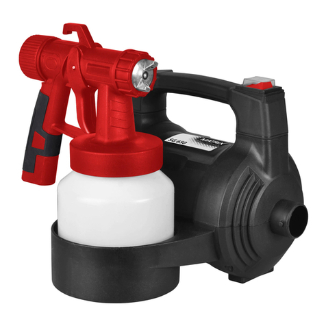
Matrix SG 650 Translation of the original instructions
Anest Iwata
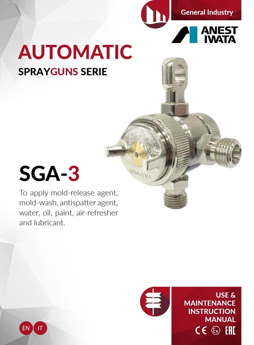
Anest Iwata SGA-3 Installation, use & maintenance instruction manual

paasche
paasche VV Instructions and parts list