Specflue DW30 User manual

DW30 by

1
Specflue DW30
Product information
Specue DW30 has been specically designed to
meet the requirements of today’s clean burning
multi-fuel appliances. The system provides an
economical and robust twin wall insulated stainless
steel chimney system oering high material
specication, design, manufacturing quality,
thermal performance and ease of installation. It is
suitable for negative draught conditions where the
maximum continuous ue gas temperature does
not exceed 600°C and is soot re rated at 1000°C.
Specue DW30 is available in 130 and 150mm
internal diameters and consists of adaptors,
lengths, ttings, supports and restop components.
Each chimney element is fabricated with a fully
welded 316L stainless steel inner liner and a
stainless steel outer case. It is also available in
a Matt Black nish as indicated by the MB sux
on the part number. The 30mm annulus between
the two walls is insulated with a high thermal
performance pressure injected or pipe section
mineral wool to a mean density of 170-190kg/
m3. The jointing system is a simple push t
male and female joint with the male end pointing
upwards. The 70mm of engagement oers a strong
structural joint with the locking band provided.
Specue DW30 is designed to be used both
internally and externally as a fully supported
structure, and must be installed in accordance
with National and Local Building Regulations and
Standards.
Approvals
Specue DW30 is tested, approved and CE marked
to BS EN 1856-1:
T600 N1 D V2 L50050 G60
60mm distance
to combustibles
in a combustible shaft
T600 N1 D V2 L50050 G50
50mm distance
to non-combustibles
in a non-combustible shaft
CE Certicate No. 0432-CPR-00593-01
Chimney Diameter
Internal diameter Outside diameter
130mm 190mm
150mm 210mm
The chimney diameter size should be as
recommended by the appliance manufacturer and
in accordance with current building regulations.
Warranty
Specue DW30 carries a 25 years conditional
warranty.
General Design Considerations
Chimney Diameter/Height
The internal diameter of the chimney must conform
to the requirements of the heating appliance
manufacturer’s instructions, and should not, under
any circumstance, be less than the appliance
outlet. The height of the chimney will depend on the
building structure, however it is recommended that
not less than 4.5 metres should be considered the
minimum chimney height from the appliance
to termination for solid fuel applications. For
further clarication refer to Document J of the
DOE Building Regulations, Section F of the
Building Standards (Scotland) and Section L
of the Building Regulations (Northern Ireland).
Chimney Route
The chimney system should remain as straight as
possible through its vertical run but should it be
necessary to oset the chimney there should be
no more than 4 changes of direction of a maximum
45°. It is also recommended that a vertical rise of
600mm should be allowed immediately above the
appliance before any change of direction.
Chimney Support
The chimney must be adequately supported
throughout its length and the Specue DW30
product oers a range of lateral and vertical
support components to undertake the safe
installation of the chimney system.

2
Provision for Sweeping
and Cleaning
Adequate provision should be made for
inspecting and cleaning the chimney system.
This is particularly important for solid fuel
applications. Specue recommends that
chimneys are swept at least once a year.
At the time of sweeping it is important that a
visual inspection of the ue is undertaken.
Combustion Air Requirements
All heating appliances need combustion air to
work eciently and safely. It is essential that the
appropriate permanent air supply, as required
by the appliance manufacturer and Building
Regulations is provided into the room where the
appliance is situated. Always refer to the appliance
manufacturer’s recommendations and Building
Regulations before installation.
Floor Penetration Components
Where the Specue DW30 product is used on solid
fuel or oil appliances and the ue gas temperature
exceeds 250°C, the clearance at oor/ceiling void
must be established using the ventilated support
plate and ventilated re shield, ensuring that no
joints are made within the ceiling void. A magnetic
re shield cover is also available used in conjunction
with the ventilated re shield to improve aesthetics.
When connecting to a single wall ue pipe,
Specue DW30 must project below the appliance
room ceiling by a minimum of 425mm before a
connection is made. All support components
oer a 60mm clearance to combustible material
that must be maintained at all times.
Appliance Connection and
Condensate Removal
The Specue DW30 adaptor should be used
to facilitate connection from the appliance to
the chimney. It is recommended that the joint
between the adaptor and the appliance/ue pipe
is securely caulked and sealed with bre rope/
tape and re sealant. Any ue pipe connection
to the chimney must be made in the same room.
Condensation removal should be determined by
each individual application. The system must be
designed to facilitate future appliance removal.
Note: In the UK, connection to an appliance
which is not connected to the fuel supply,
may be carried out by a competent person.
However, connection to an appliance connected
to the fuel supply must be carried out by an
approved and registered Heating Engineer, e.g.
Gas Safe, HETAS (solid fuel) or OFTEC (oil).
Adjustable Pipes
The Adjustable Pipe consists of two sections which
telescope together. Both sections are insulated, and
the component is supplied with additional insulation,
which will need to be added to the annulus on
site depending on the desired nished length. The
overlapping section should be secured with self
drilling screws. Each end of the adjustable pipe is
secured with locking bands in the normal manner.
The adjustable pipe does not load bear so always
use a wall support or a support plate immediately
above this component when vertically applied.
Handling
The product is relatively easy to handle, but care
should be taken when holding, tting or assembling
any part of the system. Users are advised to wear
gloves to avoid injury or any sharp exposed edges.
Data Plate
It is a regulatory requirement that a data plate
is to be completed, positioned and secured
by the installer where a hearth, replace, ue
or chimney is provided or extended. The data
plate provides essential information regarding
the performance, specication, designation and
installation of the chimney system. The data
plate is to be completed by the installer using an
indelible ink and securely xed in an unobtrusive
but obvious position. Acceptable xing positions
would be next to the electricity consumer unit,
water supply stop cock or by the hearth.
Carbon Monoxide Alarm
Approved Document J of the Building
Regulations (Section 2.34) state that all new and
replacement solid fuel appliances must be tted
with an approved carbon monoxide alarm.
3
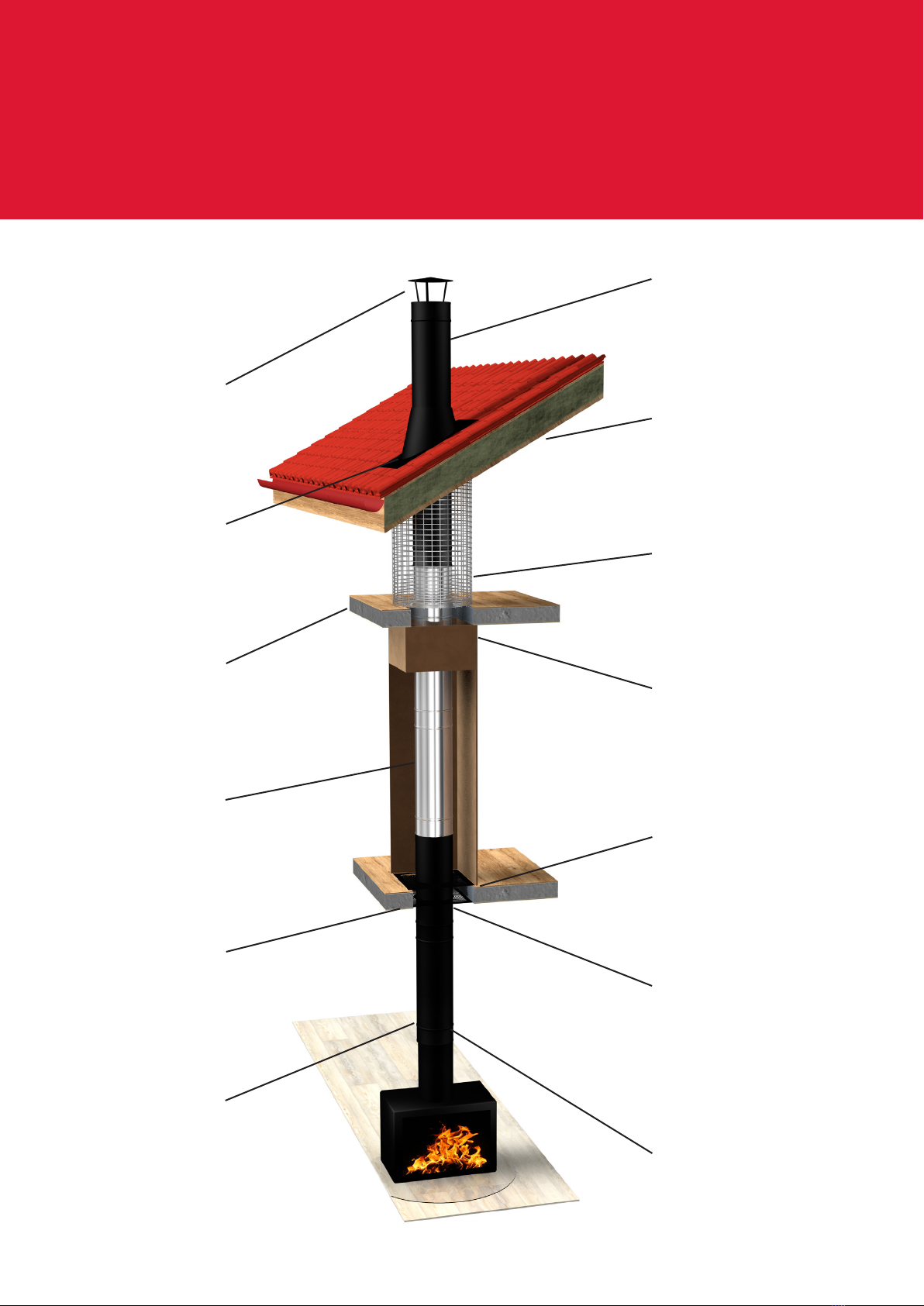
Internal Installation Diagram
Matt Black Finish
BS 9004
Roof Support
Flue Enclosure Kit
Ventilated
Fire Shield
Ventilated Support
Plate (Square)
Ventilated Fire
Shield (Round)
Matt Black Finish
in Exposed Areas
Rain Cap
Flashing +
Storm Collar
Combustible Floor
Stainless Finish
in Closed Areas
Magnetic Fire
Shield Cover
Adjustable Pipe Allow
Appliance Removal
4
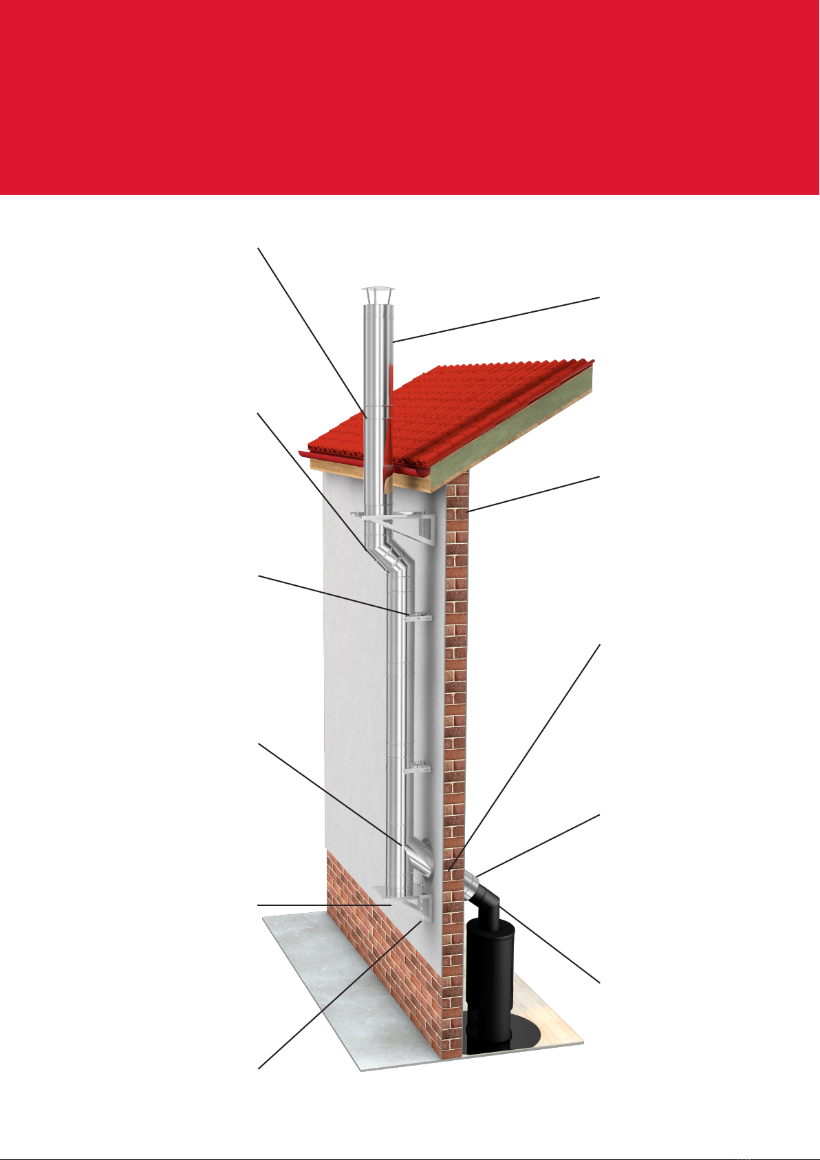
External Installation Diagram
Termination
Height to ADJ
Adj Wall Support
Wall Sleeve
Specvit to DW30
Adaptor
Specvit
Locking Bands
Bends
Adj Wall Band
135 Tee
Tee Cap
(Extended) Wall Support

5
Starting Components
Used to connect DW30 to an appliance
socket and/or connecting pipe.
Starting Adaptor
Part No A B L
0105094 130 190 124
0105094MB 130 190 124
Used to connect DW30 to an appliance socket and/
or connecting pipe, increasing up in diameter.
Increasing Adaptor
Part No A B L
105097 130 190 99
0105097MB 130 190 99
0106097 150 210 124
0106097MB 150 210 124
Used to connect DW30 to Specvit connecting
pipe and/or an appliance socket.
Specvit to DW30 Adaptor
Part No A B L
0106098 130 190 151
0106098MB 130 190 151
Used to connect DW30 to Prima Smooth
connecting pipe and/or an appliance socket.
Prima Smooth to DW30 Adaptor
Part No A B L
0105099 130 190 149
0106099MB 130 190 149
6
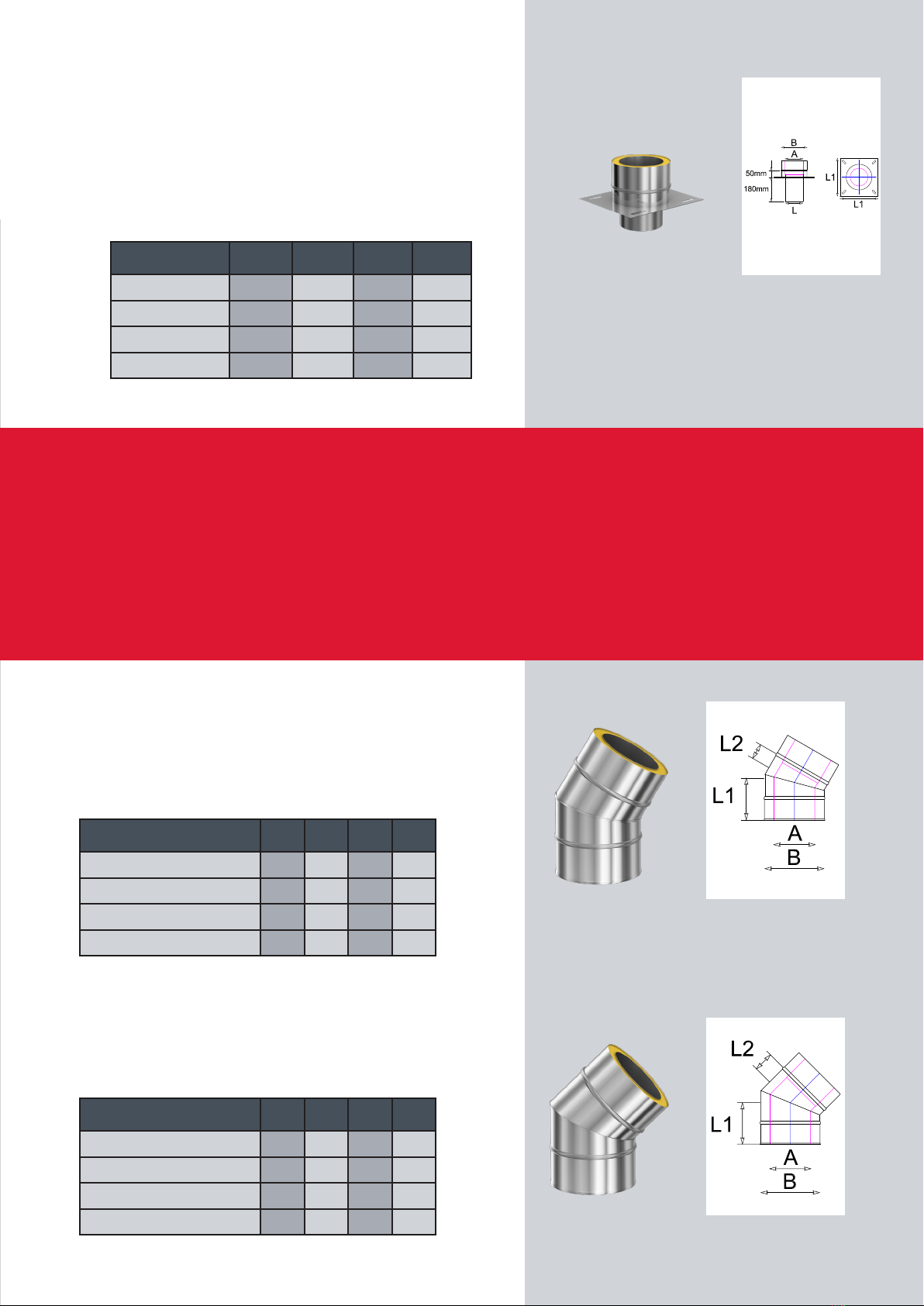
Used to connect DW30 to a raft lintel. Can also
be used at the top of an existing chimney stack
where the termination section has been removed.
DW30 ue components will sit on brickwork and
multifuel exible liner (155mm only) ts below.
Secured to the top of the stack by suitable xings.
Anchor Plate
Part No A B L L1
0105089 130 190 280 130
0105089MB 130 190 280 130
0106089 150 210 300 150
0106089MB 150 210 300 150
Bends
Provides a change of direction within the system.
Angle measured from the vertical. See table on
page 19 for oset data.
30 Degree Bend
Part No A B L1 L2
0105023 130 190 120 50
0105023MB 130 190 120 50
0106023 150 210 123 53
0106023MB 150 210 123 53
Provides a change of direction within the system.
Angle measured from the vertical. See table on
page 19 for oset data.
45 Degree Bend
Part No A B L1 L2
0105022 130 190 134 64
0105022MB 130 190 134 64
0106022 150 210 138 68
0106022MB 150 210 138 68

7
Lengths
80mm Pipe (Installed)
Part No A B L
0105006 130 190 80
0105006MB 130 190 80
0106006 150 210 80
0106006MB 150 210 80
180mm Pipe (Installed)
Part No A B L
0105012 130 190 180
0105012MB 130 190 180
0106012 150 210 180
0106012MB 150 210 180
430mm Pipe (Installed)
Part No A B L
0105005 130 190 430
0105005MB 130 190 430
0106005 150 210 430
0106005MB 150 210 430
930mm Pipe (Installed)
Part No A B L
0105002 130 190 930
0105002MB 130 190 930
0106002 150 210 930
0106002MB 150 210 930
Pipe (Installed)
Straight pipe length – installed length of
80/180/430/930mm. Actual component
is 70mm longer than installed length.

8
Used to create specic lengths where standard pipes
will not t. Supplied with insulation pads which must
be cut to length and installed within the cavity to
ensure a fully insulated product. This component
must not be installed within a oor/ceiling void.
300-430mm Adjustable Pipe (Installed)
Part No A B L1 L2
0105016 130 190 300 430
0105016MB 130 190 300 430
0106016 150 210 300 430
0106016MB 150 210 300 430
430-780mm Adjustable Pipe (Installed)
Part No A B L1 L2
0105015 130 190 430 780
0105015MB 130 190 430 780
0106015 150 210 430 780
0106015MB 150 210 430 780
Used to provide access for cleaning and inspection.
430mm Inspection Pipe (Installed)
Part No A B L
0105013 130 190 380
0105013MB 130 190 380
0106013 150 210 380
0106013MB 150 210 380
Used to ensure a secure joint between components.
Supplied with all items with a male/female tting.
Tightening screws with a 4.0mm Hex head.
Locking Band
Part No A B L
0105086 130 190 82
0105086MB 130 190 82
0106086 150 210 82
0106086MB 150 210 82
Adjustable Pipe (Installed)
9
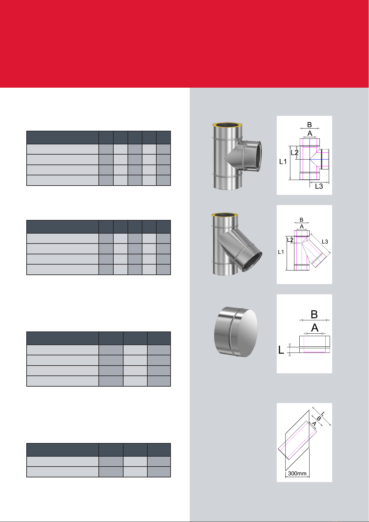
Tees Used at the base of a vertical rise, or to
provide access. Not supplied with tee cap.
90 Degree Tee
Part No A B L1 L2 L3
0105043 130 190 330 130 185
0105043MB 130 190 330 130 185
0106043 150 210 330 130 195
0106043MB 150 210 330 130 195
135 Degree Tee
Used to cap o the base or branch of a tee.
Will also t the bottom of any pipe or bend.
Tee Cap
Part No A B L
0105091 130 190 35
0105091MB 130 190 35
0106091 150 210 35
0106091MB 150 210 35
Used to provide an uninterrupted run
through a non-combustible wall.
Wall Sleeve (non combustible wall)
Part No A B L
0105051 130 190 250
0106051 150 210 280
Part No A B L1 L2 L3
0105044 130 190 430 85 345
0105044MB 130 190 430 85 345
0106044 150 210 430 75 355
0106044MB 150 210 430 75 355
Table of contents
Other Specflue Wood Stove manuals

Popular Wood Stove manuals by other brands


WoodPro
WoodPro WS-TS-1500 owner's manual

Contura
Contura C 586W installation instructions

Nordpeis
Nordpeis N-20 T user manual

Palazzetti
Palazzetti EVA GENERAL INFORMATION - WARNINGS - INSTALLATION - MAINTENANCE

Lopi
Lopi 1250 Republic owner's manual

Panadero
Panadero CAPRI 3V Usage and maintenance instructions


