Sound Performance Lab 2053 User manual

24/96 AD-DA Converter
Manual
Model 2053

Manual 24/96 AD-DA Converter 2053
224/96 AD-DA Converter 2053
Version 1.0 – 8/2000
The information in this document has been carefully
verified and is assumed to be correct. However Sound
Performance Lab (SPL) reserves the right to modify the
product described in this manual at any time.Changes
without notice. This document is the property of SPL
and may not be copied or reproduced in any manner,
in part or full without the authorization of SPL.
Limitations of Liability:
In no event will SPL be liable for any damages, inclu-
ding loss of data, lost profits, cost of cover or other
special, incidental, consequential or indirect damages
arising from the use of the unit, however caused and
on any theory of liability.This limitation will apply even
if SPL or an authorized dealer has been adviced of the
possibility of such damage.
Sound Performance Lab
P.O.Box 12 27
D- 41368 Niederkruechten,Germany
Phone +49 - 21 63 / 98 34-0
Fax +49 - 21 63 / 98 34-20
eMail: info@soundperformancelab.com
www.soundperformancelab.com
© 2000 SPL electronics GmbH. All Rights Reserved.

Contents
3
24/96 AD-DA Converter 2053
Security Advices ................................................................ 4
Product Description ......................................................... 4
Mounting
General Information ................................................. 5
Steps 1 and 2 .............................................................. 6
Steps 3 and 4 .............................................................. 7
Connections ........................................................................ 8
Analog XLR Outputs ................................................ 8
Digital I/Os .................................................................. 9
Operation
Scope of Functions ................................................... 9
AD MODE Switch ...................................................... 10
ERROR-LEDs ............................................................... 10
External Synchronization ....................................... 11
Applications
Channel One: Using both converters .................. 12
Ch.One: Using both channels of the converter 12
24Bit/96 kHz Monitoring ........................................ 13
Analog processing of a digital signal ................. 13
Example 1: Processing a sampler’s signal .......... 14
Example 2: Recording on a DAT Recorder .......... 14
Specifications ..................................................................... 15
Block Diagram .................................................................... 16
Measurements ................................................................... 17
Warranty .............................................................................. 19

Security Advices
424/96 AD-DA Converter 2053
• Please consider referring the installation of the unit
operating the converter the safety information in the
corresponding operation instruction.
• Please carry out the self-installation only as descri-
bed from page 5.In case of queries please contact an
expert.
The SPL converter module 2053 combines separately
useable A/D and D/A converters, with a wordwidth up
to 24 Bits, and a Sample-rate of up to 96 kHz.
The D/A converter processes up to 24 Bits automati-
cally, as well as sample-rates from 32Bit to 96 kHz and
is equipped with high-quality, balanced XLR outputs
(+ 12 dBu).
The A/D converter supports 16 and 24Bit formats
and works. The reduction from 24Bit to 16Bit is
processed with the Dithering-method: the "missing"
lower 8Bit is not cut off,but rather "included" in the 16
Bit format. This ensures that quietest passages are
preserved.
Internal Synchronization: The converter module
allows to choose 5 different clock sources via the AD
MODE switch.The internal sample rates (96 kHz/48 kHz
and 88.2 kHz/44.1 kHz) are Quartz-generated.
Product Description

5
24/96 AD-DA Converter 2053
External synchronization: For synchronization with
external sources, AES-data or Word-Clock signals can
be used as sync sources. Alternatively the A/D
converter can be synchronized to the data adjacent to
the D/A converter. For internal/external synchroniza-
tion please refer to the chapter "Operation", from
page 11.
The SPL converter module 2053 is exclusively offered
as an option for certain SPL units.We especially advise
electronically inexperienced users to contact an
expert in case of queries.
• In order to avoid static loads, please deactivate the
GND-Lift switch on the back of the unit that is to be
upgraded and touch its case.
• Now pull the power cord out of the socket on the
back of the unit operating the converter module.
Please also remove all other cable connections.
• Treat the converter carefully. Please make sure that
you only touch the front panel or the sides of the cir-
cuit board in order to avoid contact with parts on the
circuit board.Never force any parts when connecting
unit and converter module.
Product Description
Mounting
General Information

Mounting Steps 1 and 2
624/96 AD-DA Converter 2053
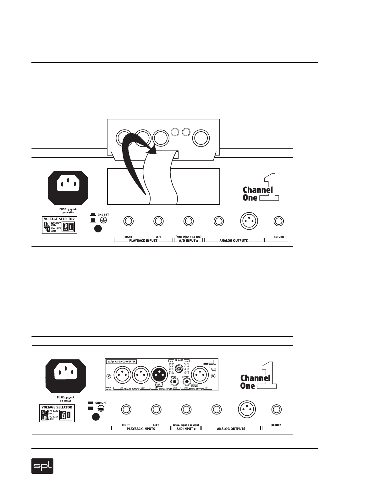
Step 1: Please put the converter module as illust-
rated on the unit top and remove the screws of the
cover from the back of the upgrade unit.
Step 2: Please remove the mounting of the wiring on
the back of the cover (eventually cut off the silicon).
Socket
Socket
Connector
Mounting
Steps 3 and 4
7
24/96 AD-DA Converter 2053
Step 3: Connect the cable carefully,without turning,
to the socket of the converter. Guideways on socket
and plug exclude a wrong connection.
Step 4: Put the converter, as illustrated, without
lateral turning in the unit (circuit board above,
connection sockets on the head) and connect it with
the screws of the cover. The converter is now opera-
tional.
Sockel

Connections
824/96 AD-DA Converter 2053
The converter module provides analog, balanced XLR
outputs (1), digital XLR I/Os (AES/EBU) (2) and digital
S/P-DIF I/Os (3). In case of using the S/P-DIF output as
a WC/AES SYNC input, the S/P-DIF output is no longer
available. Important: please never use AES- and S/P-
DIF digital inputs simultaneously!
Analog XLR Outputs
The unit operating
the module has to
be switched off
before connecting the
converter via the XLR
outputs with other units.
The illustration to the left
demonstrates the correct
wiring for unbalanced
operation.
13
2
1=GND 2=hot(+) 3=cold (-)
Balanced Unbalanced
Wiring XLR Output
1 = GND, 2 = hot (+), 3 = cold (-)
12
3

Connections
9
24/96 AD-DA Converter 2053
Digital I/Os
AES/EBU: Inputs and outputs according to the
AES/EBU specification for the connection of all digital
units specified in accordance to AES/EBU.
S/P-DIF: Alternatively to the digital XLR-sockets, the
S/P-DIF I/Os can be used for the connection of digital
units.The S/P-DIF output (=WC/AES SYNC INPUT) can
also be used for external synchronization via external
clocks (refer to "Applications, external synchroniza-
tion" on page 11).
In contrast to usual concepts, the SPL converter 2053
comprises separate A/D and D/A converter stages.
First of all the converter is determined for the optional
equipping of the SPL CHANNEL ONE (mono channel
strip). The possible applications generally described
concern all future SPL units which are determined for
the recording of the converter. Equipping both
converter stages offers two essential advantages:
• High-quality monitoring in 24Bit/96kHz quality with
simultaneous A/D conversion
• Analog processing of a digital signal
Operation
Scope of Functions

Operation
10 24/96 AD-DA Converter 2053
AD MODE Switch
The AD MODE switch is used to set the
desired bit mode and sample rate.The follo-
wing list explains the respective switch
positions:
16 Bit Mode
E = AES Ext. Synchronization to AES clock
D = DA Synchronization zum D/A converter
C = WC Ext. Synchronization to word clock
B = 48 Int. Synchronization to 48 kHz
A = 44,1 Int. Synchronization to 44,1 kHz
9 = 96 Int. Synchronization to 96 kHz
8 = 88,2 Int. Synchronization to 88,2 kHz
24 Bit Mode
0 = 88,2 Int. Synchronization to 88,2 kHz
1 = 96 Int. Synchronization to 96 kHz
2 = 44,1 Int. Synchronization to 44,1 kHz
3 = 48 Int. Synchronization to 48 kHz
4 = WC Ext. Synchronization to word clock
5 = DA Synchronization to D/A converter
6 = AES Ext. Synchronization to AES clock
Error LEDs
The Error-LEDs indicate faulty audio signals at the S/P-
DIF input or faulty sync signals at the WC/AES SYNC
INPUT (=S/P-DIF output). In this case the respective
signal is muted.
Table of contents
Other Sound Performance Lab Media Converter manuals


