Sony BKP-7933 User manual

S-BUS INTERFACE BOARD
BKP-7933
INSTALLATION MANUAL
1st Edition (Revised 1)

!WARNING
This manual is intended for qualified service personnel only.
To reduce the risk of electric shock, fire or injury, do not perform any servicing other than that
contained in the operating instructions unless you are qualified to do so. Refer all servicing to
qualified service personnel.
!WARNUNG
Die Anleitung ist nur für qualifiziertes Fachpersonal bestimmt.
Alle Wartungsarbeiten dürfen nur von qualifiziertem Fachpersonal ausgeführt werden.Um die
Gefahr eines elektrischen Schlages, Feuergefahr und Verletzungen zu vermeiden, sind bei
Wartungsarbeiten strikt die Angaben in der Anleitung zu befolgen.Andere als die angegeben
Wartungsarbeiten dürfen nur von Personen ausgeführt werden, die eine spezielle Befähigung
dazu besitzen.
!AVERTISSEMENT
Ce manual est destiné uniquement aux personnes compétentes en charge de l’entretien. Afin
de réduire les risques de décharge électrique, d’incendie ou de blessure n’effectuer que les
réparations indiquées dans le mode d’emploi à moins d’être qualifié pour en effectuer d’autres.
Pour toute réparation faire appel à une personne compétente uniquement.

1 (E)
BKP-7933
Table of Contents
Manual Structure
Purpose of this manual ........................................................................................ 3 (E)
Related manuals................................................................................................... 3 (E)
Trademarks .......................................................................................................... 3 (E)
1. Installation
1-1. Checking ROM Version........................................................................1-1 (E)
1-2. Configuration of BKP-7933..................................................................1-1 (E)
1-3. Installation Procedure............................................................................1-1 (E)
1-4. Setting Switches on the IF-689 Board ..................................................1-2 (E)
1-5. Installation.............................................................................................1-4 (E)
1-5-1. Installing the IF-689 Board ..................................................1-4 (E)
1-5-2. Installing the Rear Panel ......................................................1-5 (E)
1-6. Connection ............................................................................................1-6 (E)
1-6-1. Connection Connector/Cable ...............................................1-6 (E)
1-6-2. Connector Input/Output Signals...........................................1-7 (E)
1-6-3. Notes on Connection ............................................................1-8 (E)
1-6-4. Instance of System Configuration ........................................1-9 (E)
1-7. Setting Up............................................................................................1-10 (E)
1-7-1. Outline................................................................................1-10 (E)
1-7-2. Linking the RCP Assignment and VE Monitor Selection ....1-12 (E)
1-7-3. Linking the MSU Camera Selection
and the VE Monitor Selection............................................1-15 (E)
1-7-4. Switching the Video on the Preview Monitor
with the RCP PREVIEW Switch .......................................1-18 (E)
1-7-5. Executing RCP Assignment
from Equipment Other Than MSU ....................................1-22 (E)
1-7-6. Switching the MSU Camera Selection Externally .............1-25 (E)
1-7-7. Changing the Camera Assignment Virtually .....................1-27 (E)
1-7-8. Using the Tally System ......................................................1-29 (E)
1-7-9. Displaying the Self-diagnostic Information
on the Terminal ..................................................................1-32 (E)
1-7-10. Returning the Setups of the MODIFICATION
COMMAND to the Factory Default Values ......................1-33 (E)
1-7-11. Returning the Setups of the MAINTENANCE
COMMAND to the Factory Default Values ......................1-33 (E)
1-7-12. Connecting 13 or More Cameras .......................................1-34 (E)
1-8. Data Backup/Restore...........................................................................1-35 (E)
1-8-1. Installing the BZR-10.........................................................1-35 (E)
1-8-2. Data Backup (Uploading) ..................................................1-36 (E)
1-8-3. Data Restore (Downloading)..............................................1-38 (E)

2 (E) BKP-7933
1-9. Modification of RCP ...........................................................................1-39 (E)
1-9-1. Checking ROM Version .....................................................1-39 (E)
1-9-2. Modification of RCP-700/701............................................1-39 (E)
1-9-3. Modification of RCP-720 ...................................................1-41 (E)
1-9-4. Modification of RCP-721 ...................................................1-42 (E)
1-9-5. Modification of RCP-730/731............................................1-43 (E)
1-10. Using the BKP-7933 in the HD System..............................................1-44 (E)
1-10-1. Controlling the Routing Switcher
via the RS-422A Interface..................................................1-44 (E)
1-10-2. Controlling a Waveform Monitor ......................................1-46 (E)
1-11. Description on Internal Indicators.......................................................1-48 (E)

3 (E)
BKP-7933
Purpose of this manual This manual is the installation manual for S-BUS Interface Board BKP-7933.
This manual describes the information items necessary when the unit is supplied and
installed.
Relative manuals Besides this installation manual the following manuals are available for this unit.
..
..
.BKP-7933 Maintenance Manual (Available on request)
This manual describes the information items that premise the service based on the
components parts such as alignment, schematic diagrams, board layouts and spare
parts lists, assuming use of service engineers.If this manual is required, please
contact your local Sony Sales Office/Service Center.
..
..
.CNU-700 Operation Manual (Supplied with CNU-700)
This manual is necessary for application and operation of CNU-700.
..
..
.CNU-700 Maintenance Manual (Supplied with CNU-700)
This manual describes the information items necessary when CNU-700 is supplied
and installed, items that premise the service based on the components parts such as
schematic diagrams, board layouts and spare parts lists, assuming use of system
and service engineers.
..
..
.DVS-V1616/A3232B/V6464B/RS1616/TC3232/A3232,
BVS-V3232/A3232, HDS-V3232
Installation Manual (for System Setup)
(supplied with each unit)
It contains information on the initial settings of the software when installing the
above units making up the digital router system.
This manual is intended for system and service engineers, but operators can also
refer to it when setting and changing the system.
..
..
.BVP-900-series System Manual BKP-9901 (Available on request)
This manual is necessary for connection and operation of CNU-700 and other
peripheral equipment, and for setup to control the routing switcher in the HD
system.
If this manual is required, please contact your local Sony Sales Office/Service
Center.
Trademarks Trademarks and registered trademarks used in this manual are follows.
.MS-DOS is a registered trademark of Microsoft Corporation.
.Windows is a registered trademark of Microsoft Corporation.
.IBM and AT are registered trademarks of International Business Machine, Inc.
Manual Structure


1-1 (E)
BKP-7933
Section 1
Installation
1-1. Checking ROM Version
When the BKP-7933 is installed in the CNU-700, be sure to check that the ROM versions for IC4 and
IC5/AT-89 board of the CNU-700 are Ver. 3.00 or higher. If the ROM needs to be replaced, contact your
local Sony Sales Office/Service Center.
ROM Version
IC4/AT-89 board Ver. 3.00 or higher
IC5/AT-89 board Ver. 3.00 or higher
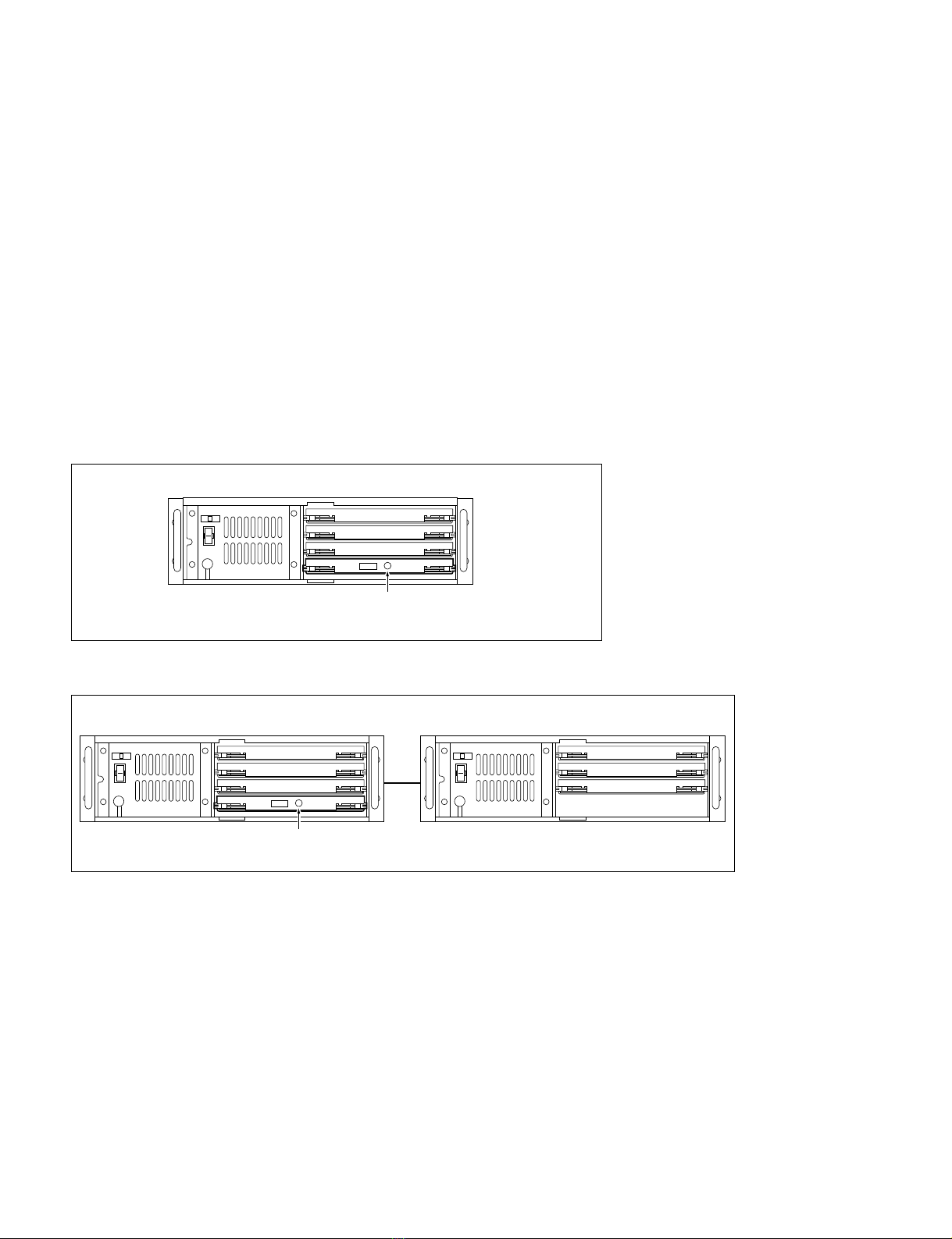
1-2. Configuration of BKP-7933
The BKP-7933 is composed of the following items.
. Main board (IF-689 board) (1)
.Rear panel (with CN-1558 board) (1)
.Installation manual (1)
1-3. Installation Procedure
This section explains briefly on installation procedures. Refer to each section for details.
Installation procedure Section
1. Checking ROM Version 1-1. Checking ROM Version
2. Switch setting on the board 1-4. Setting Switches on the IF-689 Board
3. Installation of the IF-689 board/Rear panel 1-5. Installation
4. Connection 1-6. Connection
5. Setup 1-7. Setting Up
1-9. Modification of RCP
1-10.Using the BKP-7933 in the HD System
6. Data Backup/Restore 1-8. Data Backup/Restore
1-2 (E) BKP-7933
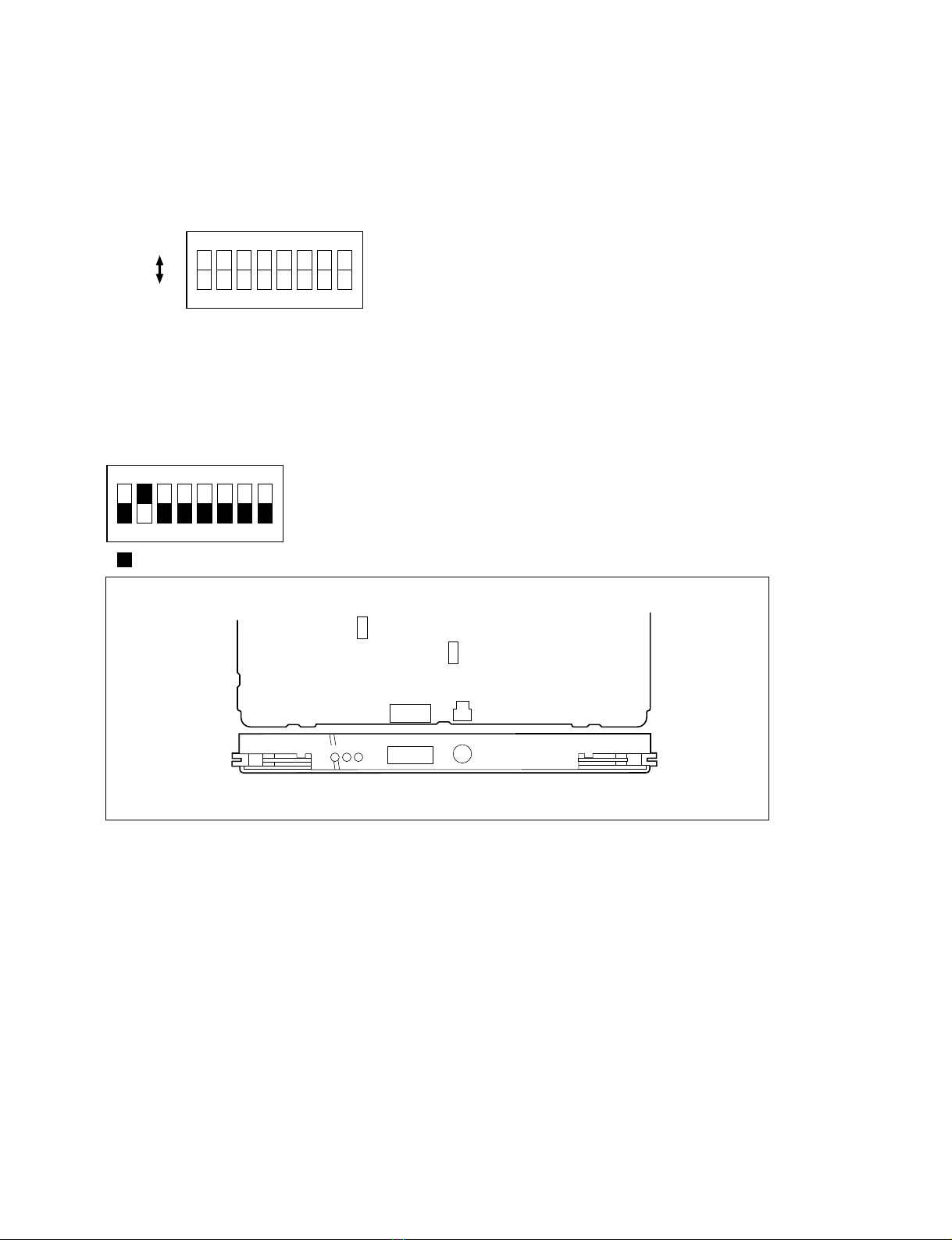
1-4. Setting Switches on the IF-689 Board
m
.Be sure make the switches settings for the CNU GROUP No. and S-BUS ID No. before turning on the
power. It is no use in setting the switches after turning on the power.
.Do not change the following switches from their factory default settings.
S5-8: OFF
S201: 1(ON)
Setting of CNU GROUP No.
S3(CNU GROUP No.)
Set the CNU GROUP No. so that it should be unique in a system.
Factory default setting: 2
Setting Examples
1. When installing the BKP-7933 in the CNU-700 which is provided with the BKP-7930
2. When using the two CNU-700s which are provided with the BKP-7930
1-4. Setting Switches on the IF-689 Board
CNU GROUP No. 0 (IF-480)
CNU GROUP No. 1 (IF-480)
(IF-689)
Set CNU GROUP No. to 2
CNU GROUP No. 0 (IF-480)
CNU GROUP No. 1 (IF-480)
(IF-689)
Set CNU GROUP No. to 4
CNU GROUP No. 2 (IF-480)
CNU GROUP No. 3 (IF-480)
CNU-700 (2)
AUX1
CNU-700 (1)
1-3 (E)
BKP-7933
18765432
1()128643216842
S-BUS ID No.
Setting example
13: 0000001
064: 0100000
1(ON)
0(OFF)
Setting of S-BUS ID No.
S12 (S-BUS ID No.)
Set the station address for the unit on the standard S-BUS data link.
n
Set to numbers other than 0, 1 and 255.
Factory default setting: 2
18765432
( indicates the switch lever position)
1-4. Setting Switches on the IF-689 Board
(Component side/A side)
IF-689 board
IF RX TX
S-BUS
S-BUS ID No.
S201
S5
S3
S12
CNU GROUP No.
+5
1-4 (E) BKP-7933
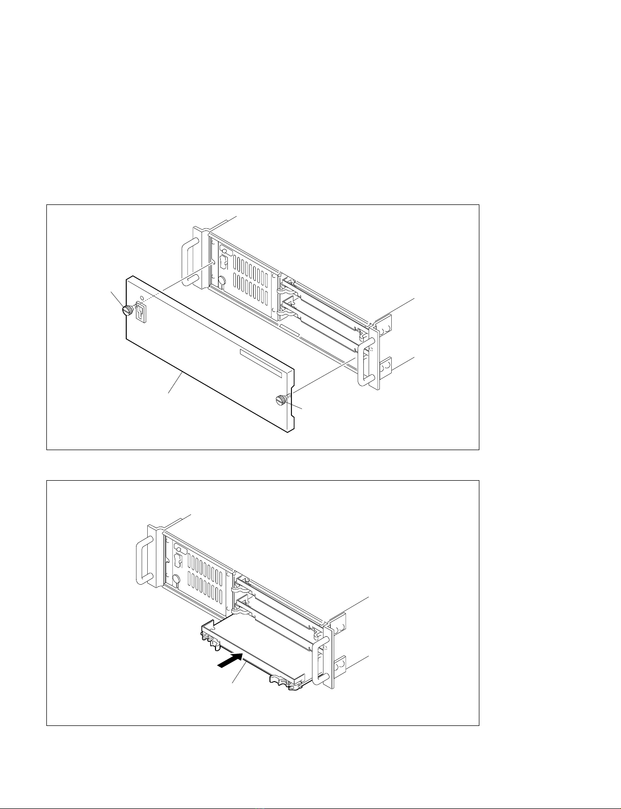
1-5. Installation
1-5-1. Installing the IF-689 Board
n
The unit is equipped with shielding springs which have sharp edges. Do not touch them with bare hands.
Pay careful attention when servicing.
1. Loosen the two screws and remove the front panel of the CNU-700.
2. Insert the IF-689 board in the fourth slot from the top.
3. Attach the front panel to its original position.
Screw
Screw
Front panel
IF-689 board
1-5. Installation
Table of contents
Other Sony Recording Equipment manuals

Sony
Sony XE-90 MkII User manual

Sony
Sony RCD-W222ES - Cd/cdr Recorder User manual

Sony
Sony SEQ-711 User manual

Sony
Sony BDX-N1000 User manual

Sony
Sony DSR-DU1 User manual

Sony
Sony HDW-1800 User manual

Sony
Sony DPS-V55 User manual

Sony
Sony SRMASTER SR-PC4 User manual

Sony
Sony BKM-103 User manual

Sony
Sony SRW-1 User manual

Sony
Sony SLV-E510EE User manual

Sony
Sony PCM-R300 User manual

Sony
Sony PCM-R300 User manual

Sony
Sony PCMD1 - Professional XLR Microphone Preamp User manual

Sony
Sony MU-R201 User manual

Sony
Sony SRW-5000 User manual

Sony
Sony SEG-2550 User manual

Sony
Sony PCM-3348HR User manual

Sony
Sony FLEXICART BFC-1 User manual

Sony
Sony DFR-E3000 User manual


