Sony BKMA-720 User manual

HDCAM INPUT BOARD
BKMA-720
INSTALLATION MANUAL
1st Edition
Serial No. 10001 and Higher

!WARNING
This manual is intended for qualified service personnel only.
To reduce the risk of electric shock, fire or injury, do not perform any servicing other than that
contained in the operating instructions unless you are qualified to do so. Refer all servicing to
qualified service personnel.
!WARNUNG
Die Anleitung ist nur für qualifiziertes Fachpersonal bestimmt.
Alle Wartungsarbeiten dürfen nur von qualifiziertem Fachpersonal ausgeführt werden. Um die
Gefahr eines elektrischen Schlages, Feuergefahr und Verletzungen zu vermeiden, sind bei
Wartungsarbeiten strikt die Angaben in der Anleitung zu befolgen. Andere als die angegeben
Wartungsarbeiten dürfen nur von Personen ausgeführt werden, die eine spezielle Befähigung
dazu besitzen.
!AVERTISSEMENT
Ce manual est destiné uniquement aux personnes compétentes en charge de l’entretien. Afin
de réduire les risques de décharge électrique, d’incendie ou de blessure n’effectuer que les
réparations indiquées dans le mode d’emploi à moins d’être qualifié pour en effectuer d’autres.
Pour toute réparation faire appel à une personne compétente uniquement.
BKMA-720

1 (E)
BKMA-720
Table of Contents
Manual Structure
Purpose of this manual ........................................................................................ 3 (E)
Related manuals................................................................................................... 3 (E)
Contents ............................................................................................................... 3 (E)
1. Installation
1-1. Overview ............................................................................................... 1-1 (E)
1-2. Board Installation .................................................................................. 1-2 (E)
1-2-1. In the Case of 2-IN and 2-OUT ............................................ 1-2 (E)
1-2-2. In the Case of 3-IN and 1-OUT ............................................ 1-5 (E)
2. Service Overview
2-1. Description of Internal Switches and Indicators ................................... 2-1 (E)
2-1-1. ENC-72 Board ...................................................................... 2-1 (E)
2-2. Specifications ........................................................................................ 2-3 (E)


3 (E)
BKMA-720
Manual Structure
Purpose of this manual
This manual is the installation manual of the BKMA-720 HDCAM input board.
This manual is intended for use by trained system and service engineers, and
describes the information regarding installation.
Related manuals
Besides this Installation Manual, the following manuals are available for the
BKMA-720.
..
..
.MAV-777 Maintenance Manual (Available on request)
This manual describes the information that premises the service based on parts
replacement (maintenance functions, parts replacement, electrical alignment, and
circuit descriptions, parts list, block diagrams, etc.).
If this manual is required, please contact your local Sony Sales Office/Service
Center.
Contents
The following is a summary of all the section for understanding the contents of this
manual.
Section 1 Installation
Explains the overview of the BKMA-720, how to install the BKMA-720 to the
MAV-777.
Section 2 Service Overview
Explains the internal switches and indicators, specifications of the BKMA-720.


1-1 (E)
BKMA-720
Section 1
Installation
1-1. Overview
The HDCAM input board BKMA-720 can expand the number of input and output ports of the multi-
access video disk recorder MAV-777 to 3-IN and 1-OUT by installing the 2 pieces of the BKMA-720.
When one piece of the BKMA-730 and another piece of the BKMA-720 are installed, the number of
input and output ports of the multi-access video disk recorder MAV-777 can be expanded to 2-IN and 2-
OUT.
The ENC-72 board processes the 2 channels of the video/audio input signals.
The BKMA-720 consists of the following:
.BKMA-720 main unit
.Harness 2 pcs
.Installation manual
.Operation guide

1-2 (E) BKMA-720
Top panel
Screws (with drop-safe)
Power supply unit
Slot No. 1
Slot No. 11
Main board retainer
Screw (with drop-safe)
Screw
(with drop-safe)
A
Cover
Harness
Tie band
Bend
DEC-136 board
Slot No. 6
CN1502 (6 Blue)
CN1501 (13 Black)
CN202 (7)
CN200 (8)
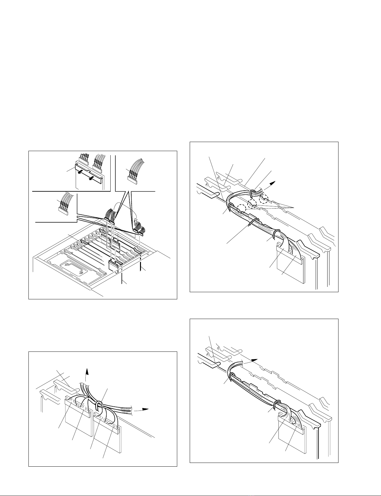
4. Pull the harnesses out that are housed in the slots Nos.
5 and 6.
5. While bending the shaded portion of the cover as
shown in the illustration inside, remove the harnesses
in the direction of arrow A from the slot.
6. Cut the tie band that bundles the harness.
7. Insert the DEC-136 board in the slot No. 6.
8. Connect the four harnesses as shown in the following
table among the harnesses that are removed in step 4,
to the DEC-136 board so that the colors and the
numbers indicated match with the harness colors and
numbers on the board.
Board connector Indication of the harness
(Cap color)
CN1501 13 (Black)
CN1502 6 (Blue)
CN200 8 (_)
CN202 7 (_)
1-2. Board Installation
n
The slot that is nearest to the power supply unit is assigned
as the slot No. 1. In the MAV-777, the PU-109 board is
inserted in the slot No. 1. The slots are assigned starting
from No. 1 up to No. 13 in this order.
1-2-1. In the Case of 2-IN and 2-OUT
n
Add one piece of the BKMA-720 board (ENC-72 board)
and one piece of the BKMA-730 board (DEC-136 board)
respectively.
1. Turn off the power of the MAV-777.
2. Loosen the two screws (with drop-safe), and remove
the top panel.
3. Loosen the two screws (with drop-safe), and remove
the main board retainer.
1-2. Board Installation

1-3 (E)
BKMA-720
12. While closing the board levers in the direction of
arrow 1, push in the circuit board deep into the end
of the slot securely.
n
Be careful not to pinch the harnesses between the board le-
ver and the board. If it is pinched, it may cause open circuit.
13. While opening the connector clamp with finger by
pushing it in the direction of the arrow, connect the
two harnesses that are supplied with the BKMA-720,
to the EM-4 board and to the DEC-136 board in the
slot No. 6 referring to the illustration below.
m
.Insert the connectors of the harnesses into the board
connectors in the way that the metallic side of the
harness connectors are facing the circuit boards.
.After the harnesses are connected, push the connector
clamps that are opened before, with finger until the
connectors of the supplied harnesses are hidden.
11
DEC-136 board
Slot No. 6 Board levers
ENC-72 board
Slot No. 5
CN203 (7 Green)
CN202 (3 Amber)
CN1 (5)
CN2 (6)
11
ENC-72 board
Slot No. 5 Board levers
Connector
clamp
Slot No. 6
DEC-136 board
EM-4 board
Supplied harness
Supplied harness
Black
Red
9. While closing the board levers in the direction of
arrow 1, push in the circuit board deep into the end
of the slot securely.
n
Be careful not to pinch the harnesses between the
board lever and the board. If it is pinched, it may cause
open circuit.
10. Insert the ENC-72 board in the slot No. 5.
11. Connect the four harnesses as shown in the following
table among the harnesses that are removed in step 4,
to the ENC-72 board so that the colors and the num-
bers indicated match with the harness colors and
numbers on the board.
Board connector Indication of the harness
(Cap color)
CN202 3 (Amber)
CN203 7 (Green)
CN1 5 (_)
CN2 6 (_)
1-2. Board Installation
1-4 (E) BKMA-720
14. While opening the connector clamps with finger by
pushing it in the direction of the arrow, connect the
two harnesses that are supplied with the BKMA-720,
to the EM-4 board and to the ENC-72 board in the slot
No. 5 referring to the illustration below.
m
.Insert the connectors of the harnesses into the board
connectors in the way that the metallic side of the
harness connectors are facing the circuit boards.
.After the harnesses are connected, push the connector
clamps that are opened before, with finger until the
connectors of the supplied harnesses are hidden.
15.
Secure the harnesses using the wire clamp of the board.
(1) Secure the harnesses coming from the DEC-136 board
and the ENC-72 board in a way that the harnesses
cross each other, with the wire clamp (one clamp) on
the EM-4 board in the slot No. 10.
Connector
clamp
Slot No. 5
EM-4 board
ENC-72 board
Supplied harness
Supplied harness
Red
Black
1-2. Board Installation
(2) Secure the harnesses coming from the EM-4 board
with the three wire clamps on the DEC-136 board in
the slot No. 6. When securing the harnesses, fix the
center wire clamp in the direction shown by the
illustration in order to avoid interference with the main
board retainer.
(3) Secure the harnesses connecting the EM-4 board to the
DEC-136 board in the slot No. 6, with the wire clamp
(one clamp) on the ENC-72 board in the slot No. 8.
When securing the harness, route the harnesses through
the recessed portion of the board up to the board lever A.
(4)
Secure the harnesses coming from the EM-4 board with the
two wire clamps on the ENC-72 board in the slot No. 5.
Slot No. 5
(ENC-72 board)
Slot No. 10
(EM-4 board)
Slot No. 6
(DEC-136 board)
Wire clamp
Black
Black
Red
Red
Slot No. 8
(ENC-72 board)
Slot No. 10
(EM-4 board)
Slot No. 6
(DEC-136 board)
Wire clamp
Red
Black
Wire clamp
Wire clamp
(Secure the harness avoiding
projection of the board.)
Wire clamp
Recessed portion
Board lever A
Slot No. 5
(ENC-72 board)
Slot No. 10
(EM-4 board)
Wire clamp
Wire clamp
Red
Black
Table of contents
Other Sony I/O System manuals


