Sony XM-7527 X-Plod User manual
1
MICROFILM
XM-7527
US Model
Canadian Model
AEP Model
UK Model
E Model
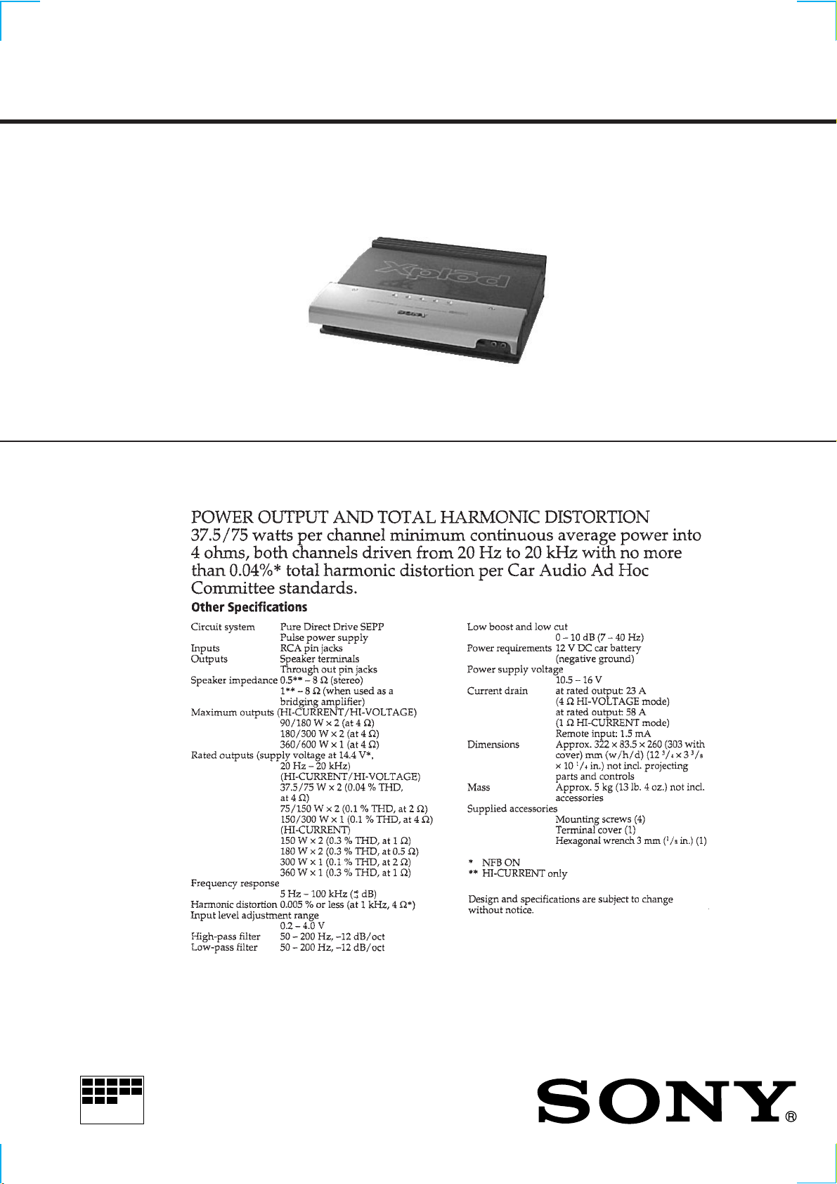
SPECIFICATIONS
SERVICE MANUAL
STEREO POWER AMPLIFIER

2
TABLE OF CONTENTS
1. SERVICE MODE ............................................................. 3
2. GENERAL .......................................................................... 4
3. DISASSEMBLY
3-1. Side Plate and Bottom Plate.................................................. 7
3-2. Amplifier/Power Board and LED Board .............................. 7
4. ELECTRICAL ADJUSTMENT .................................... 8
5. DIAGRAMS
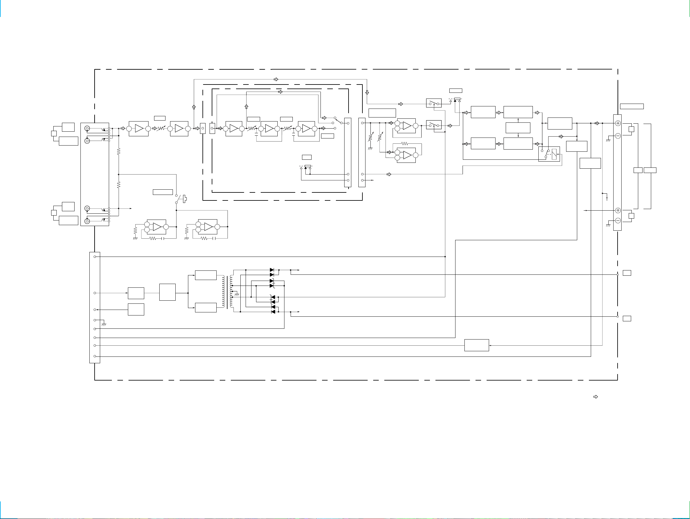
5-1. Block Diagram – Amplifier Section – .................................. 9
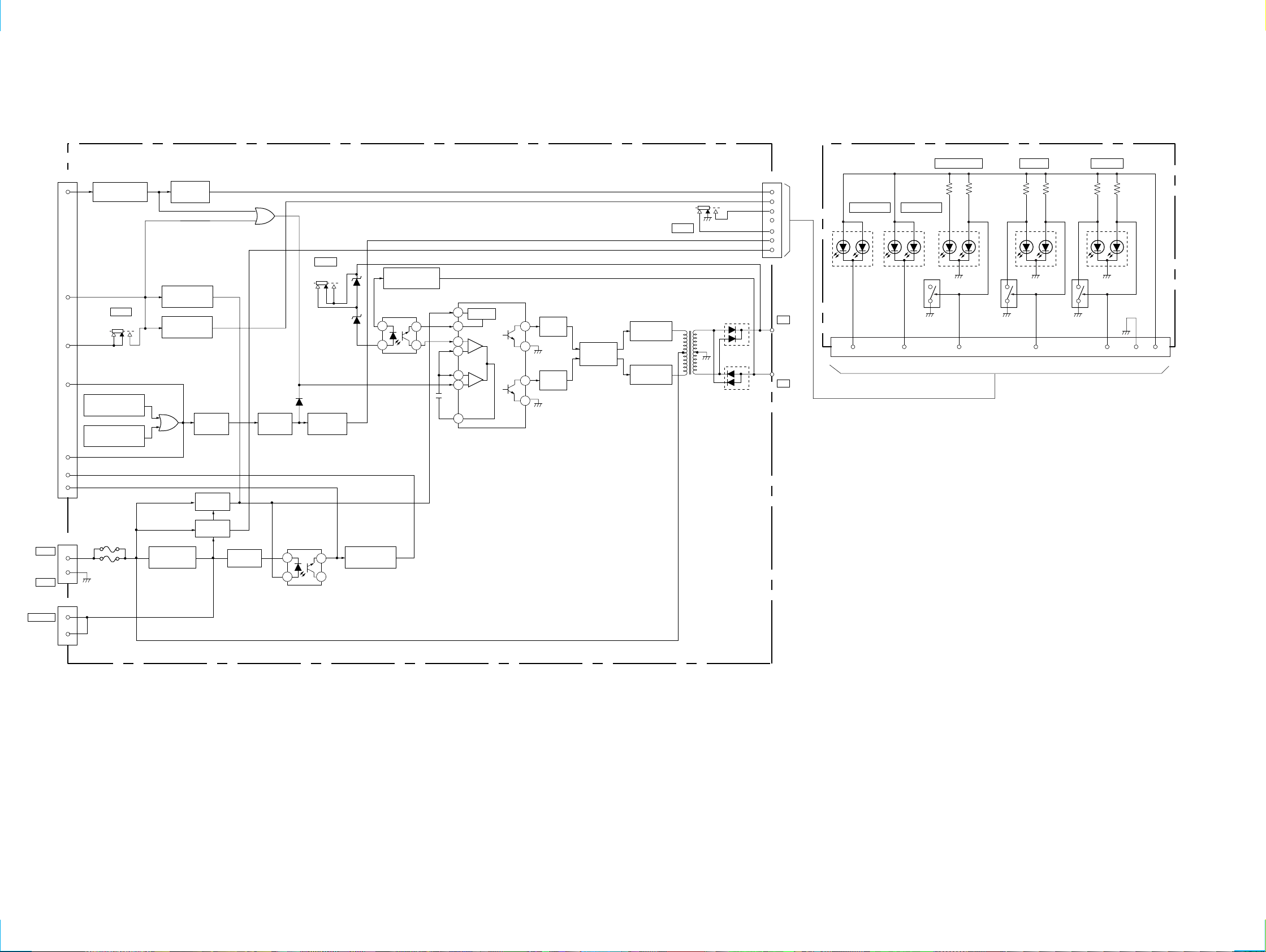
5-2. Block Diagram – Power Section – ...................................... 10
5-3. IC Block Diagram ............................................................... 11
5-4. Printed Wiring Board – Filter/Amplifier Section –............. 12
5-5. Schematic Diagram – Filter/Amplifier Section – ............... 13
5-6. Printed Wiring Board – Power Section – ............................ 14
5-7. Schematic Diagram/Printed Wiring Board
– LED/Power Section – ...................................................... 15
6. EXPLODEDVIEWS
6-1. Plate and Cover Section ...................................................... 16
6-2. Board and Heat Sink Section .............................................. 16
7. ELECTRICAL PARTS LIST ........................................ 17
Notes on chip component replacement
• Never reuse a disconnected chip component.
• Notice that the minus side of a tantalum capacitor may be
damaged by heat.

3
SECTION 1
SERVICE NOTE
Clearing the Protector During Repairs
• OVER CURRENT : Detects overcurrent during output.
• OFF SET : Detects DC offset at the speaker terminal.
1. Clearing the OVER CURRENT protector
1When the position of the MODE switch (S801/power board)
is set to HI-VOLTAGE :
Cut the jumper wire JW065 of the amplifier board.
2When the position of the MODE switch (S801/power board)
is set to HI-CURRENT :
Cut the jumper wire JW066 of the amplifier board.
2. Clearing the OFF SET protector
• Cut the jumper wire JW024 of the amplifier board.
3. TESTTONE Function
1Press the TESTTONE button (S805/amplifier board) with the
power ON. The amplifier is normal if sound is produced from
the speaker.
2If no sound
: Problem causer by incorrect connecttion of the power supply
system or sperker system.
: The signals input by the RCAcable before the amplifier system
are abnormal.
Adjustment Location:
VR201 VR101
JW066JW065
JW024
S805
TEST TONE
- POWER BOARD - (Component side) - AMPLIFIER BOARD - (Component side)
S801
MODE

4
SECTION 2
GENERAL This section is extracted from
instruction manual.
5
6

7
SECTION 3
DISASSEMBLY
Note: Follow the disassembly procedure in the numerical order given.
3-1. SIDE PLATE AND BOTTOM PLATE
3-2. AMPLIFIER/POWER BOARD AND LED BOARD
1
Two screws
(BTP3x8)
0
Two screws
(BTP3x8)
4
Screw
(BTP3x8)
5
Filter board
2
Three screws
(BTP3x8)
6
Two screws
(BTP3x8)
!¢
Two screws
(M4)
3
Bottom plate
Heat sink block
!§
Auto fuse (F901)
!¶
Auto fuse (F902)
9
Side panel (L)
!£
Side panel (R)
!™
Screw (BTP3x8)
7
Screw (BTP3x8
)
8
Screw (BTP3x8)
!¡
Screw (BTP3x8)
!∞
Cover
2
Two screws
(P4X40)
8
Three screws
(P3X8)
!£
Two insulating sheets
(AMP)
!™
Sub heat sink
(Amplifier)
!¡
Three screws
(P3X6)
9
Two screws
(P3X14)
3
Three screws (BVTP3X14)
0
Screw (BTP3X8)
1
Three screws (BTP3x12)
5
Screw (BVTP3X10)
4
Retainer
6
Power board
7
Amplifier board
!¢
Two screws (BTP 2x10)
!∞
LED board
!§
LED holder

8
SECTION 4
ELECTRICAL ADJUSTMENTS
Idling Current Adjustment
• Perform adjustments in the HI-VOLTAGE mode.
1Adjustment point
Semi-fixed resistors VR101, VR201 of amplifier board.
2Precautions on adjustments
1. Set the RCA input terminal to open.
2. Apply a voltage of 14.4Vbetweenthe+12Vterminal,REMOTE
terminal, and GND terminal.
3. Rotate the above semi-fixed resistors completely in the coun-
terclockwise direction while observing the component side.
4. Check that the voltage at the adjustment point becomes 0 mV
in step 2.
5. Fine adjustments may be required according to the characteris-
tics of the MOS-FET used.
• When adjusting the idling current
Rotating the semi-fixed resistor in the clockwise direction:
In creases the idling current
Rotatingthesemi-fixedresistorin the counterclockwisedirection:
Decreases the idling current
* Take note that rotating excessively in the clockwise direction
will increase the idling current suddenly.
3Approximate adjustment values
Adjust as follows so that the following voltages become
0.4 to 0.5 mV .
L channel :
Voltage between TP101 and TP102: Use VR101 of the ampli-
fier board
R channel :
Voltage between TP201 and TP202: Use VR201 of the ampli-
fier board
Digital voltmete
r
TP101(L-CH)
TP201(R-CH)
TP102(L-CH)
TP202(R-CH)
- AMPLIFIER BOARD - (Component side)
Adjustment Location
Connection :
IDLING
(R-CH) VR201 VR101 (L-CH)
TP202
TP201
TP102
TP101
XM-7527
9
9
SECTION 5
DIAGRAMS
5-1. BLOCK DIAGRAM – AMPLIFIER SECTION –
5 7 6 7
88
12 12
11 11
5 7 6 7 6 7 5
67
7
DIFFERENTIAL
AMP
Q104,106
DIFFERENTIAL
AMP
Q103,105
POWER AMP
(VOLTAGE STAGE)
Q108
BIAS
VR101
OVERLOAD
Q112,113
OVERLOAD
Q114-115
OFFSET
DET
Q812-814
CNJ805
6
3
5
4
1
9
7
8
CNP804
POWER AMP
(VOLTAGE STAGE)
Q107
POWER AMP
(FINAL STAGE)
Q110-111
NFB ON
NFB OFF
RY801(1/2)
DIRECT
SW802(1/2)
LINE SWITCH
Q102
LINE SWITCH
Q101
LOWBOOST
IC102(1/2)
LOWBOOST
IC102(2/2)
POWER
DRIVE
Q942
THERMAL
DET
TH803
POWER
CONTROL
Q941
INVERTER
Q943
R-CH R-CH
CN807
SPEAKER OUT
ON OFF
PRE AMP
IC801(1/2) H.P.F
IC802(1/2)
H.P.F
IC101(2/2)
IC201(2/2) L.P.F
IC803
L.P.F
IC101(1/2)
IC201(1/2)
LEVEL
VR801(1/2) FILTER
VR804 FILTER
VR804
CNP806
CNJ806
CNJ806 CNP806HPF
LPF
FLAT
INVERTER
Q944
B+
B-
T902 D942
D944
D946
D948
D947
D945
D943
D949
R-CH
R-CH
L-CH
TO
POWER
BOARD
CNB804
09
FILTER BOARD
AMPLIFIER BOARD
31
TEST TONE AMP
IC804(1/2) TEST TONE AMP
IC804(2/2)
FILTER
ON OFF
B+
SW803
L
L+R MONO
R
INPUT
(M0N0)
OUTPUT
(THROUGH)
L
INPUT
OUTPUT
(THROUGH)
R
257
6
TEST TONE
S805
NFB
S804
11
VR802
(2/4) VR802
(1/4)
5
6
BOOST/LOWCUT
FREQ
VR802
+28V
TO
POWER
BOARD
B+
-28V
B-
• Signal path
: Audio
XM-7527
10
10
5-2. BLOCK DIAGRAM – POWER SECTION –
7
8
9
2
4
6
5
CNB804
CNJ802
CNJ801
TO
AMPLIFIER
BOARD
CNP804
GND
REMOTE
4
3
1
2
5
7
CNP803
POWER BOARD
OFFSET CONTROL
Q805-806 OFFSET LED
SWITCH
Q811
THERMAL DETECTOR
TH801
THERMAL DETECTOR
TH802
B+ SWITCH
Q904
B+ SWITCH
Q902
THERMAL
CONTROL
Q801
THERMAL
SWITCH
Q802
THERMAL
LED SWITCH
Q809
11
10
1
2
15
16
3
8
9
12
14
REF-REG
THERMAL SWITCH
TH901,Q915
DRIVER
Q906 INVERTER
Q910,912,914
DRIVER
Q905
INVERTER
Q909,911,913
T901
SWITCHING
CONTROL
Q907-908
F902 (25A)
F901 (25A)
S801
HI-VHI-C
+28V
-28V
TO
AMPLIFIER
BOARD
D904
D903
IC902
DC DET
IC903
DC SWITCH
DC-DC
CONVERTER
IC901
OVER CURRENT
CONTROL
Q807-808
OVER CURRENT
LED SWITCH
Q810
D803
OR
D806
OR
D802
S801
MODE
HI-C HI-V
S801
D905
D906
HI-V
HI-C
D845
HI-VOLTAGE D844
HI-CURRENT
D843
OVER CURRENT
G
1 7
GGR
D842
OFFSET
GR
D841
THERMAL
GR
B+
Q843
SWITCH Q842
SWITCH Q841
SWITCH
CNB803
LED BOARD
09
MODE
MODE
+12V
B+ SWITCH
Q903
POWER ON/OFF
D901,Q901 REGULATOR
D804,Q803-804
B+
B-
1 4
3
2
1 4
3
2
Other manuals for XM-7527 X-Plod
2
Table of contents
Other Sony Amplifier manuals

Sony
Sony XM-3001SXD - Stereo Power Amplifier User manual

Sony
Sony TA-F5000 User manual

Sony
Sony XM-GS4 User manual

Sony
Sony XK-R100 User manual

Sony
Sony TA-DX80 User manual

Sony
Sony TA-VA7ES User manual

Sony
Sony TA-VE800G User manual

Sony
Sony TA-S9D User manual

Sony
Sony TA-N80ES User manual

Sony
Sony TA-VE800G Specification sheet


