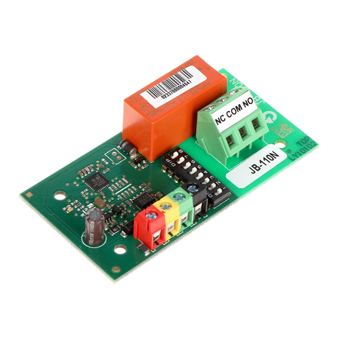
Solar-Log MOD I/O User manual

Connections
Top Bottom
For further information on connecting the ripple control receiver, please refer
to the installation manual.
Quick Start Guide
MOD I/O
Introduction
This installation manual is intended for use by solar energy technicians and
professional electricians, as well as Solar-Log Base users. It should be noted
that the installation and commissioning of the individual components is only to be
performed by properly trained specialists.
The Solar-Log™ must only be used by persons who have fully read and under-
stood this manual before installing, operating and/or servicing the device.
Please observe!
Disconnect the power of the Solar-Log Base before plugging in/out the bus
connector and before connecting the module with the Solar-Log™.
Assembly
The MOD I/O module is manufactured in accordance with protection class IP20
and is designed exclusively for installation in suitable for dry, dust-free indoor use.
The assembly itself can be carried out both via wall mounting as well as on a DIN
rail. Power is supplied via the bus system by the Solar-Log Base, a power supply
via pins power + and - is not required for the PM+ function. The need of an exter-
nal power supply is optional and depends on the output current.
Module MOD I/O connection and mounting
Take one of the 2 bus connectors included in the scope of delivery. The bus con-
nector is plugged into the back of the Solar-Log Base.
Take the second bus connector and plug it into the back of the MOD I/O.
To complete the HBus connection, plug the two bus connectors together.
Now the connected housings can be snapped into the DIN rail.
Follow the short instructions Solar-Log Base.
Technical Data
Device voltage 24V (+-5 %), in exceptional cases 12V (+-5 %)
Total current of the outputs With a power supply via the HBus: 250 mA
With an external power supply: 1A
Cable cross-section
Solid conductor: 0.2 … 1.5 mm² / 24 … 16 AWG
Fine-stranded conductor: 0.2 … 1.5 mm² / 24 … 16 AWG
With ferrules: 0.14 ... 1 mm²/ 26 ... 18 AWG (ferrules
– to be used for fi ne-stranded conductor)
Strip length 8.5 … 9.5 mm / 0.33 … 0.37 inch, with ferrules ≧ 6mm / 0,24 inch
Please take into account the diameter of the plastic sleeves
Power consumption min. 2 W
Control signal Voltage of the control signal corresponds to
Supply voltage of the Solar-Log Base
Dimensions (Wx-
HxD) in mm 53,6x89,7x60,3
Solare Datensysteme GmbH • www.solar-log.com • Subject to change without notice • EN | 11.2020 | Version 1.4 | Art.Nr.: 15818
Pin MOD I/O
COM Functional earthing
1Control signal active power
2Digital_In 1
3Digital_In 2
4Digital_In 3
5Digital_In 4
6Control signal reactive power
COM Functional earthing
Currently without function Power
65 4 321
Without function
PM+
COM
COM
- +

Kurzanleitung
MOD I/O
Einleitung
Diese Kurzanleitung richtet sich an Solarteure und Elektrofachkräfte sowie
an Benutzer des Solar-Log Base. Es sei darauf hingewiesen, dass die Instal-
lation und Inbetriebnahme der einzelnen Komponenten nur von den dafür aus-
gebildeten Fachkräften vorgenommen werden darf. Die ausführenden Personen
(Installation, Bedienung und Wartung) müssen die Anleitung vollständig gelesen
und vollständig verstanden haben.
Bitte beachten!
Unterbrechen Sie die Stromversorgung des Solar-Log Base vor dem Ein-
oder Ausstecken der Busverbinder und vor dem Verbinden des Moduls mit
dem Solar-Log™.
Montage
Das Modul MOD I/O ist nach Schutzklasse IP20 gefertigt und ausschließlich für
die Montage im trockenen, staubfreien Innenbereich geeignet. Die Montage
selbst kann sowohl über Wandmontage als auch auf einer Hutschiene erfolgen.
Die Stromversorgung erfolgt über das Bussystem durch den Solar-Log Base, eine
Spannungsversorgung über die Pins Power + und - wird für die PM+ Funktion
nicht benötigt. Netzteil optional Abhängig vom Ausgangstrom.
Modul MOD I/O Verbindung und Montage
Nehmen Sie einen der 2 im Lieferumfang enthaltenen Busverbinder. Der
Busverbinder wird auf der Rückseite des Solar-Log Base eingesteckt. Nehmen
Sie den zweiten Busverbinder und stecken diesen auf der Rückseite des MOD
I/O ein. Um die HBus Verbindung fertigzustellen, stecken Sie die beiden Bus-
verbinder zusammen. Nun können die verbunden Gehäuse in die Hutschiene
eingerastet werden.
Beachten Sie die Kurzanleitung Solar-Log Base.
Anschlüsse
Oberseite Unterseite
Weitere Informationen zum Anschluss des Rundsteuerempfängers entneh-
men Sie bitte dem Installationshandbuch.
Pin MOD I/O
COM Funktionserde
1Steuersignal Wirkleistung
2Digital_In 1
3Digital_In 2
4Digital_In 3
5Digital_In 4
6Steuersignal Blindleistung
COM Funktionserde
Technische Daten
Gerätespannung 24V (+-5 %), bei Bedarf 12V (+-5 %)
Summenstrom
der Ausgänge Bei Versorgung über HBus: 250mA
Bei ext. Spannungsversorgung: 1A
Leiterquerschnitt
Eindrähtiger Leiter: 0,2 bis 1,5 mm²
Feindrähtiger Leiter: 0,2 bis 1,5 mm²
Mit Aderendhülsen: 0,14 bis 1,0 mm² (Aderendhülsen sollten bei
feindrähtigen Leitern verwendet werden.)
Abisolierlänge 8,5 - 9,5 mm, mit Aderendhülsen ≧ 6mm
Bitte beachten Sie den Durchmesser des Kunststoff kragens
Geräteleistung min. 2W
Steuersignal Spannung des Steuersignals entspricht
Versorgungsspannung des Solar-Log Base
Abmessung (BxHxT) in mm 53,6 x 89,7 x 60,3
Solare Datensysteme GmbH • www.solar-log.com • Änderungen vorbehalten • DE | 11.2020 | Version 1.4| Art.Nr.: 15818
- +
Derzeit ohne Funktion Power Ohne Funktion
PM+
65 4 321
COM
COM

Table of contents
Languages: