socomec ATyS D10 User manual
Remote interface
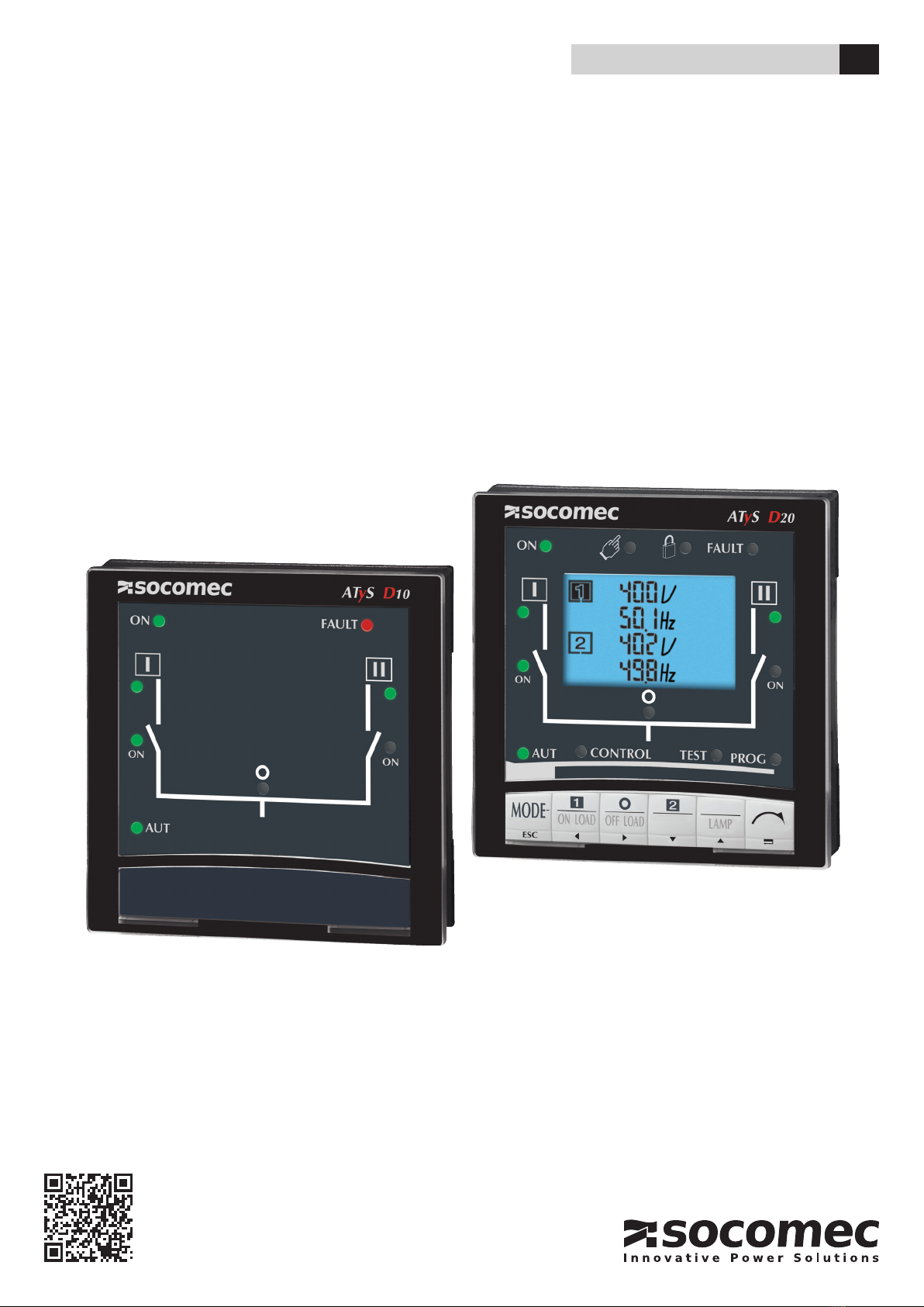
ATySD10 / D20
INSTRUCTION MANUAL EN
www.socomec.com
To download, brochures, catalogues and technical manuals.

2EN ATYS D10 / D20 - 542359B - SOCOMEC
Contents
1. PRELIMINARY OPERATIONS...............................................................3
2. GENERAL INFORMATION ..................................................................3
3. INSTALLATION ..............................................................................4
3.1. MOUNTING ...............................................................................4
3.2. CONNECTION .............................................................................4
3.3. CHARACTERISTICS........................................................................4
4. OPERATION .................................................................................5
4.1. ATYS D10 DISPLAY . . . . . . . . . . . . . . . . . . . . . . . . . . . . . . . . . . . . . . . . . . . . . . . . . . . . . . . . . . . . . . . . . . . . . . . .5
4.2. DISPLAY ATYS D20 ........................................................................6
4.2.1. KEYPAD D20 .........................................................................7
4.2.2. SOFTWARE VERSION .................................................................7
5. PROGRAMMING ATYS D20 ................................................................8
5.2.1. PROGRAMMING EXAMPLE ............................................................9
5.2.2. ARCHITECTURE OF THE PROGRAMMING MENU ATYSD20 ..............................10
5.2.2.1. ARCHITECTURE VALID FOR ATYS 6M AND ATYS 6E (MASTER) ............................10
5.2.2.2. ARCHITECTURE VALID FOR ATYS M 6E (MASTER) ......................................12
5.2.2.3. ARCHITECTURE VALID FOR ATYS P (MASTER) .........................................14
5.2.2.4. ARCHITECTURE VALID FOR ATYS C30 (MASTER) .......................................16
6. CONFIGURATION AND CHARACTERISTICS OF VARIABLES FOR THE ATYS D20.....17
7. OPERATION MODES (CONTROL OR TEST) ATYS D20 ..................................18
7.1. BROWSING ..............................................................................18
7.2. OPERATION MODES (CONTROL OR TEST) .................................................18
8. OPERATION ATYS D20 ....................................................................19
9. ATYS D20 VISUALIZATION ................................................................20
9.1. VISUALISATION MENU ARCHITECTURE ....................................................21
9.1.1. ARCHITECTURE VALID FOR ATYS 6M, ATYS 6E AND ATYS C30 (MASTER) ................21
9.1.2. ARCHITECTURE VALID FOR ATYS P (MASTER) .........................................22
9.2. EVENTS. . . . . . . . . . . . . . . . . . . . . . . . . . . . . . . . . . . . . . . . . . . . . . . . . . . . . . . . . . . . . . . . . . . . . . . . . . . . . . . . . .24

3
EN
ATYS D10 / D20 - 542359B - SOCOMEC
1. Preliminary operations
For personnel and product safety, please read the contents of these operating instructions carefully before installation.
The following points should be checked upon product receipt:
• the packing is in good condition,
• the product has not been damaged during transportation,
• the product reference number conforms to your order,
2. General information
The ATyS D10 and ATyS D20 are remote interface modules that allow an easy remote for display and/or control for
the following products:
Product ATyS master Compatible display
ATyS C30
ATyS M6e
ATyS d
ATyS t
ATyS g
ATyS p
Note :
The ATyS D10 and D20 are compatible with the previous range of ATyS 6e and ATyS 6m products.

4EN ATYS D10 / D20 - 542359B - SOCOMEC
3. Installation
3.1. Mounting
Door xing / 2 holes, diameter 22.5 mm
Maximum thickness of the door: 20 mm
ATYS 147 B
(1) RJ45 plug for ATyS connection
Ø 22.5
40 3620
==
96 x 96
ATYS 161 A 1 X CAT
Drillings
3.2. Connection
Connect only to products of type ATyS C30, ATyS M6e, ATyS d, ATyS t, ATyS g et ATyS p.
(Compatible with the old ATyS range 6e and ATyS 6m).
> Cable
RJ45 8 wire straight-through, non isolated cable. Cable length: ≤ 3m. Ref.: 1599 2009.
> Maximum length of the connection cable: 3 m
RJ45 type
RJ45 type
RJ45 type
RJ45 type
ATyS M6e ATyS M6eATyS C30 ATyS C30
ATyS D10 ATyS D20
ATyS d ATyS p
ATyS t
ATyS g
3.3. Characteristics
> IP
IP21 standard
IP54 using gasket
> Operation
Temperature: -10 to + 55 °C
Hygrometry:80 % humidity at 55 °C
95 % humidity at 40 °C
5
EN
ATYS D10 / D20 - 542359B - SOCOMEC
4. Operation
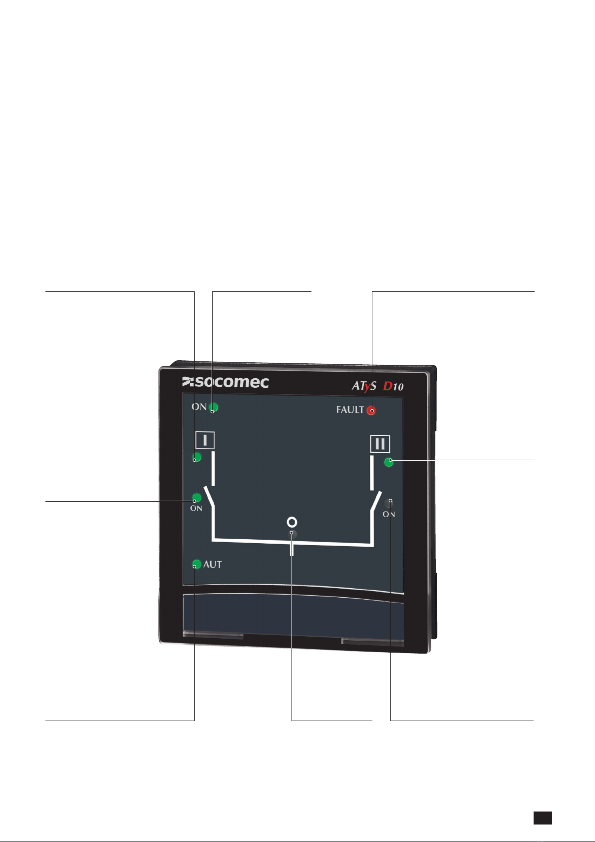
4.1. ATyS D10 display
The ATyS D10 allows remote display of the transfer switch: positions, source availability and operational modes.
Programming and operation remains available directly on the master product ATyS C30, ATyS M6e, ATyS d, ATyS t
and ATyS g
(Compatible with the old ATyS range 6e and ATyS 6m).
Source 1 available Power on
• ATyS product fault, non-conform
switching
• Possible to reset after fault is cleared.
Switch off the power supplies of the
master product for 3 minutes.
Transfer switch in
position I
Transfer switch
in automatic mode
Transfer switch in
position 0
Transfer switch in
position II
Source II available

6EN ATYS D10 / D20 - 542359B - SOCOMEC
4.2. Display ATyS D20
The ATyS D20 allows remote display of transfer switchpositions, source availability, operational modes and metering.
It also allows the control of product control and test operations as well as access to programming of all system
parameters.The display of the ATyS product is inhibited when connected to the remote interface.
(Compatible only with ATyS p and the former ATyS 6e, ATyS 6m, ATyS C30 and ATyS M 6e).
Power on
Source 1 available
Manuel
mode
active Padlock*
• ATyS product
fault, non-conform
switching
• Possible to reset
after fault is cleared.
Switch off the power
supplies of the master
product for 3 minutes.
Transfer switch in
position I
Transfer switch
in automatic mode
Control mode active Test mode active Programming mode active
Transfer switch in
position 0
Transfer switch in
positionII
Source 2 available

7
EN
ATYS D10 / D20 - 542359B - SOCOMEC
Priority source
Information
• source 1
• source 2
• sources 1 & 2 (split
screen)
Power factor Capacitive
or inductive
Phases (wires) displayed Units
Values
Power
values ±
ATyS 318 A
4.2.1. Keypad D20
Access to AUT, Test, Control
and Prog modes
Direct Access to Test and Control
functionalities or navigation Allows main menu access in
visualisation mode or validation
ATYS 146 C
4.2.2. Software version
Software version of the master product is displayed
immediately after power on.

8EN ATYS D10 / D20 - 542359B - SOCOMEC
5. Programming ATyS D20
>
Enter into programming mode
• Step 1: Press5 s “validation”: PROG led becomes steady
• Step 2: Enter access code (1000 factory default) using the keypad
"left”, “right”, “up” and “down”
• Step 3: Press the "validation" push button
>
Navigation in programming mode
• Step 1: To access the required menu, press the "right" and "left" navigation buttons
• Step 2: To access the parameter to be modified, press the "up" and "down" navigation buttons
• Step 3: To modify the parameter, press the "right" navigation button to make the parameter to be
modified flash
• Step 4: Press the "up" and "down" buttons to increase or decrease the parameter values
• Step 5: Press "validation" push button to validate
If the parameter to be modified is displayed on 2 lines, press "validate" after modifying the first line
to reach the next line
Allows to return to the main menu or to cancel the modification
>
Programming mode exit
• Step 1: Press the "ESC" push button when not entering any value, to return
to the main programming menu
• Step 2: Press on "ESC" push button again to exit programming
New Active mode (Automatic or Manual) depends on the information from the master ATyS device.
9
EN
ATYS D10 / D20 - 542359B - SOCOMEC
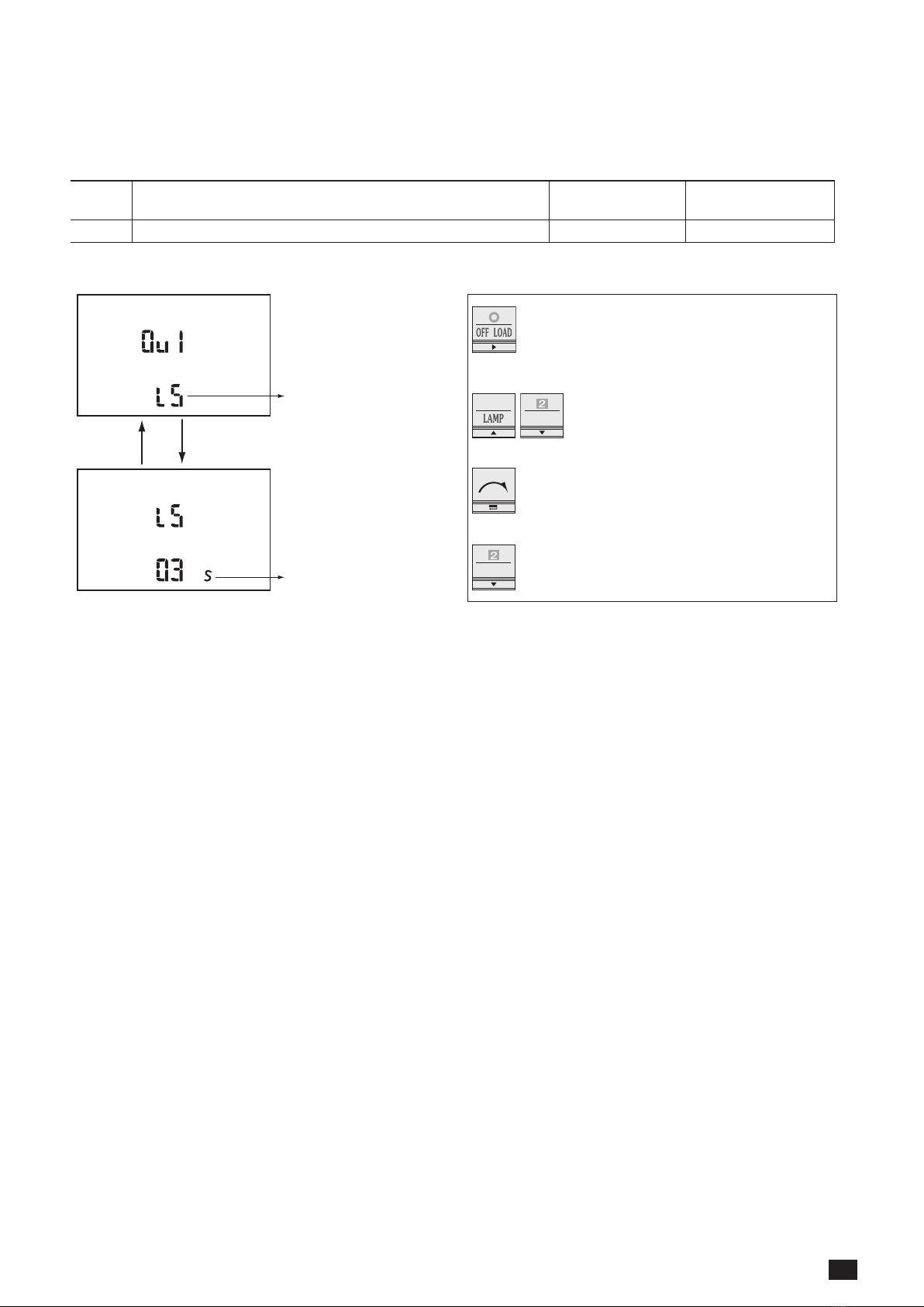
5.2.1. Programming example
Load shedding conguration: LS
LS variable allows programming the timer associated shedding.
OUT-
PUT
Function Setting range Default values
01 to n LS 0 to 60 s (≤DTT)* 2
* In case the DTT variable conguration value is below the LS, value LS will be automatically set to the DTT value.
fonction
temporisation associée
• Step 1: Press "right" push button to make
the first variable blink
• Step 2: press "up" and "down" to
modify the variable
• Step 3: Press "validate" to validate the
variable
• Step 4: Press "down" to access the nO
selection
function
timer

10 EN ATYS D10 / D20 - 542359B - SOCOMEC
5.2.2. Architecture of the programming menu ATySD20
5.2.2.1. Architecture valid for ATyS 6m and ATyS 6e (master)
(2)(2)
(2)(2)
(2)(2)
(2)(2)(2)
(2)(2)(5)
(2)(1)
(2)
(2)
(2)
(2)
(2)(3)
(2)(3)
(2)(3)
(4)
This manual suits for next models
1
Table of contents
Other socomec Recording Equipment manuals


