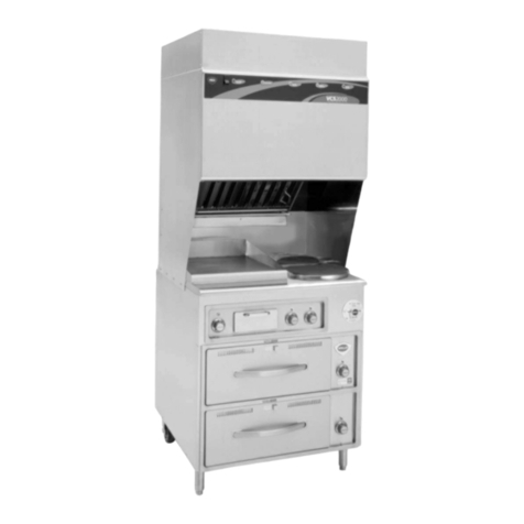
Smeg A3 User manual

Contents
39
1. INSTRUCTIONS FOR SAFE AND PROPER USE _______________40
2. INSTALLATION OF THE APPLIANCE ________________________42
3. ADAPTATION TO DIFFERENT TYPES OF GAS ________________45
4. FINAL OPERATIONS______________________________________47
5. DESCRIPTION OF CONTROLS _____________________________49
6. USE OF THE COOKING HOB_______________________________55
7. USE OF THE OVENS _____________________________________57
8. ACCESSORIES __________________________________________58
9. COOKING HINTS_________________________________________60
10. CLEANING AND MAINTENANCE ____________________________68
11. EXTRAORDINARY MAINTENANCE __________________________72
THESE INSTRUCTIONS ARE VALID ONLY FOR END USER COUNTRIES WHOSE
IDENTIFICATION SYMBOLS APPEAR ON THE COVER OF THIS MANUAL.
INSTRUCTIONS FOR THE INSTALLER: these are for the qualified
technician who must carry out a suitable check of the gas system,
install the appliance, set it functioning and carry out an inspection test.
INSTRUCTIONS FOR THE USER: these contain user advice,
description of the commands and the correct procedures for cleaning
and maintenance of the appliance.

Introduction
40
1. INSTRUCTIONS FOR SAFE AND PROPER USE
THIS MANUAL IS AN INTEGRAL PART OF THE APPLIANCE AND
THEREFORE MUST BE KEPT IN ITS ENTIRETY AND IN AN ACCESSIBLE
PLACE FOR THE WHOLE WORKING LIFE OF THE COOKER. WE ADVISE
READING THIS MANUAL AND ALL THE INSTRUCTIONS THEREIN BEFORE
USING THE COOKER. ALSO KEEP THE SERIES OF NOZZLES SUPPLIED.
INSTALLATION MUST BE CARRIED OUT BY QUALIFIED PERSONNEL IN
ACCORDANCE WITH THE REGULATIONS IN FORCE. THIS APPLIANCE IS
INTENDED FOR DOMESTIC USES AND CONFORMS TO CURRENT
REGULATIONS IN FORCE. THE APPLIANCE HAS BEEN BUILT TO CARRY
OUT THE FOLLOWING FUNCTIONS: COOKING AND HEATING-UP OF FOOD.
ALL OTHER USES ARE CONSIDERED IMPROPER.
THE MANUFACTURER DECLINES ALL RESPONSIBILITY FOR IMPROPER
USE.
DO NOT LEAVE THE PACKING IN THE HOME ENVIRONMENT. SEPARATE
THE VARIOUS WASTE MATERIALS AND TAKE THEM TO THE NEAREST
SPECIAL GARBAGE COLLECTION CENTRE.
IT IS OBLIGATORY FOR THE ELECTRICAL SYSTEM TO BE GROUNDED
ACCORDING TO THE METHODS REQUIRED BY SAFETY RULES.
IMMEDIATELY AFTER INSTALLATION CARRY OUT A BRIEF INSPECTION
TEST OF THE APPLIANCE, FOLLOWING THE INSTRUCTIONS BELOW.
SHOULD THE APPLIANCE NOT FUNCTION, SWITCH OFF THE POWER
SUPPLY TO THE APPLIANCE AND CALL THE NEAREST TECHNICAL
ASSISTANCE CENTRE.
NEVER ATTEMPT TO REPAIR THE APPLIANCE.
ALWAYS CHECK THAT THE CONTROL KNOBS ARE IN THE POSITION
(OFF) WHEN YOU FINISH USING THE HOB.
NEVER PUT INFLAMMABLE OBJECTS INTO AN OVEN: IF THEY CATCH FIRE
THEY COULD CAUSE A FIRE IN THE HOME.
THE I.D. PLATE WITH TECHNICAL DATA, REGISTRATION NUMBER AND
BRAND NAME IS POSITIONED VISIBLY IN THE STORAGE COMPARTMENT.
THE PLATE MUST NOT BE REMOVED.

Introduction
41
DURING USE THE APPLIANCE BECOMES VERY HO
T
.TAKECARENOTTO
TOUCH THE HEATING ELEMENTS INSIDE THE OVEN.
DO NOT INSTALL THIS APPLIANCE ON A RAISED PLATFORM
DO NOT PUT PANS WITHOUT PERFECTLY SMOOTH AND FLAT BOTTOMS
ON THE COOKING HOB GRIDS.
DO NOT USE CONTAINERS OR BROILERS THAT EXTEND BEYOND THE
OUTER PERIMETER OF THE HOB.
THE APPLIANCE IS DESIGNED FOR USE BY ADULTS. DO NOT ALLOW
CHILDREN TO GO NEAR OR PLAY WITH IT.
REPLACED APPLIANCES MUST BE TAKEN TO A SPECIAL GARBAGE
COLLECTION CENTRE.
The manufacturer declines all responsibility for damage to persons
or things caused by non-observance of the above prescriptions or by
interference with any part of the appliance or by the use of non-original
spares.

Instructions for the installer
42
2. INSTALLATION OFTHE APPLIANCE
It is the law that all gas appliances are installed by competent persons.
Corgi gas installers are approved to work to safe and satisfactory
standards. All gas installation, servicing and repair work must be in
accordance with the gas safety regulations 1984 (installation and use) as
amended 1990.
It can be placed against walls higher than the hob, at a distance of at
least 50 mm from the side of the appliance, as shown in the drawings A
and B relating to the installation classes. Wall units or extractor hoods
located above the hob must be at least 750 mm away from it.
A B
SLOT IN FREE STANDING
2.1 Positioning and levelling of the appliance
This appliance is fitted with 4 castors for easy positioning. To block the
appliance in tis final position, extract the feet on the front and screw the
corresponding castors in.
CAUTION: delicate floors could be damaged by the castors; in this case,
lift the appliance with a mechanical means.
2.2 Electrical connection
Make sure that the power line voltage matches the specifications
indicated on the rating plate located inside the storage compartment.
This rating plate must never be removed.
The connection to the mains shall be done conforming to the regulations
in force. Check that the power line is adequately grounded. Do not use
reducers, adapters or shunts. On the power line, install an omnipolar cut-
off device with contact cut-off distance greater than or equal to 3 mm,
located in an easily accessible position near the unit.

Instructions for the installer
43
The connection terminals are
located at the rear of the
appliance. For electrical
connections see following
diagram. To access, remove
the rear cover.
For operation on 400-415V3N
∼
∼∼
∼
:use
an H05RR-F-type five-core cable (5 x
1.5 mm2).
For operation on 400-415V2N
∼
∼∼
∼
:use
an H05RR-F-type four-
c
orecable(4x
2.5 mm2).
For operation on 230-240V
∼
∼∼
∼
:use an
H05RR-F-type three-core cable (3 x 4
mm2).
The cable end to be connected to the
appliance must be provided with an
ground wire (yellow-green) at least 20
mm longer.
The manufacturer declines all responsibility for damage to persons
or things caused by non-observance of the above prescriptions or by
interference with any part of the appliance.

Instructions for the installer
44
2.3 Ventilation requirements
The room containing the appliance should have an air supply in
accordance with B.S. 5440 part 2 1989.
1. All rooms require an opening window or equivalent, and some
rooms will require a permanent vent as well.
2. For room volumes up to 5 m3an air vent of 100 cm2is required.
3. If the room has a door that opens directly to the outside, and the
room exceeds 1 m3no air vent is required.
4. For room volumes between 5 m3and 10 m3an air vent of 50 cm2is
required.
5. If there are other fuel burning appliances in the same room B.S.
5440 part 2 1989 should be consulted to determine the air vent
requirements.
6. This appliance must not be installed in a bed sitting room of less
than 20 m3or in a bathroom or shower room.
Windows and permanent vents should therefore not be blocked or
removed without first consulting a Corgi gas installer.
Failure to install appliances correctly is dangerous and could lead
to prosecution.
2.4 Connecting to natural and LPG gas
(Please see connection diagram)
Make the connection to the appliance using flexible
bayonet style hose in accordance to B.S. 669. The
hose connection at the rear of the appliance has a
1/2" BSP internal thread. Please use seal Cbetween
the flexible connection Land the appliance supply
tube B. When making the connection, make sure that
no stress of any kind is applied to the cooker and that
the hose does not touch any sharp edges or come in
contact with the rear of the appliance.
If connecting to LPG the bayonet hose must have
red bands on it.

Instructions for the installer
45
3. ADAPTATIONTO DIFFERENTTYPES OF GAS
Before performing any cleaning or maintenance work, switch off the
power supply to the appliance.
The cooking hob of the cooker is preset for G20 natural gas at a
pressure of 20 mbar. In the case of functioning with other types of gas the
burner nozzles must be changed and the minimum flame adjusted on the
gas taps. Replace the burner nozzles as indicated in the table of the gas
to be used.
3.1 Changing nozzles
1. Extract the grids and remove all the caps and flame-spreader
crowns;
2. unscrewtheburnernozzleswitha7mmsocketwrench;
3. proceed with replacing the burner nozzles in accordance with the
table for the gas in question.

Instructions for the installer
46
3.2 Burner and nozzle characteristics table
Burner Rated
heating
capacity
(kW)
LPG – G30/G31 28/37 mbar
(drawing ref. X238)
Nozzle
diameter
1/100 mm
By-pass
Mm
1/100
Reduced
flowrate
(W)
Flowrate
g/h G30 Flowrate
g/h G31
Auxiliary 1.05 50 30 360 76 75
Semi rapid 1.8 65 33 450 131 129
Rapid 3.0 85 45 750 218 215
Fish Burner 1.9 68 45 800 138 136
Triple crown 3.3 91 68 1600 218 215
Burner Rated
heating
capacity
(kW)
NATURAL GAS – G20 20 mbar
Nozzle diameter
1/100 mm Drawing
Ref. Reduced flowrate
(W)
Auxiliary 1.05 72 (X) 360
Semi rapid 1.8 97 (Z) 450
Rapid 3.0 115 (Y) 750
Fish Burner 1.9 94 (X) 800
Triple crown 3.5 133 (S) 1600
3.3 Arrangement of burners on cooking hob
BURNERS
1 Auxiliary
2 Semi rapid
3 Rapid
4 Triple crown
5 Fish burner

Instructions for the installer
47
4. FINAL OPERATIONS
After replacing the nozzles, reposition the flame-spreader crowns, the
burner caps and the grids.
Following adjustment to a gas other than the preset one, replace the gas
adjustment label fixed to the appliance with the one corresponding to the
new gas. This label is in the packet together with the nozzles.
4.1 Adjustment of minimum for natural gas
Light the burner and turn it to the minimum
position . Extract the gas tap knob and turn the
adjustment screw at the side of the tap rod until
the correct minimum flame is achieved.
Replace the knob and check burner flame
stability: (rapidly turning the knob from maximum
to minimum position, the flame should not go
out). Repeat the operation on all the gas taps.
4.2 Regulation of minimum for LPG
For regulating the minimum with LPG, the screw at the side of the tap rod
must be turned clockwise all the way.
The bypass diameters for each individual burner are shown in paragraph
“3.2 Burner and nozzle characteristics table”. When adjustment is
complete, re-seal the by-passes using wax or an equivalent material.

Instructions for the installer
48
4.3 Mounting the rear top upstand
• Position the upstand above the top, taking care to align holes Awith
holes B.
• Secure the upstand to the top by tightening screws C.
Other manuals for A3
2
This manual suits for next models
1
Table of contents
Other Smeg Cooktop manuals

Smeg
Smeg SIM571B User manual

Smeg
Smeg HB96CXU3 User manual

Smeg
Smeg PM6912WLDXAU User manual

Smeg
Smeg SID61MFX5 User manual

Smeg
Smeg SIMU524 User manual

Smeg
Smeg C36GGRU User manual

Smeg
Smeg NKT335E Assembly instructions

Smeg
Smeg SE640ID1 User manual

Smeg
Smeg 9FALOI1 Assembly instructions

Smeg
Smeg NCT335EEU Configuration guide

Smeg
Smeg Freestanding Cooker CSA150X-6 User manual

Smeg
Smeg NCT335EEU User manual

Smeg
Smeg Portofino User manual

Smeg
Smeg PU64 User manual

Smeg
Smeg SIHP294S Technical manual

Smeg
Smeg SA9058X User manual

Smeg
Smeg SR764AO User manual

Smeg
Smeg RTU366GX User manual

Smeg
Smeg SIMU524B User manual

Smeg
Smeg PV264B User manual