Smart power Distribution Unit User manual

User’s Manual
Version 04/12
Smart Power
Distribution Unit
Remote Power Manager ("RPM")
Copyright © Smart Power Systems, All rights reserved.
Reproduction without permission is prohibited.

- i -
Table of Contents
Chapter 1: Introducing Remote Power Manager ....................................................1
1.1 Contents of Your RPM Package.................................................................................... 1
1.2 Remote Power Manager Features................................................................................ 2
Chapter 2: Hardware Setup.......................................................................................3
2.1 Basic Connection.......................................................................................................... 3
2.2 Hardware Installation Procedure................................................................................... 3
2.3 Daisy Chain Setup Procedure....................................................................................... 6
Chapter 3: RPM Setup Utility (Netility).....................................................................8
3.1 Installing Netility............................................................................................................ 8
3.2 Using Netility for IP Configurations ............................................................................... 8
3.2.1 NetWork Selection ................................................................................................. 8
3.2.2 Configure................................................................................................................ 9
3.2.3 Download Firmware............................................................................................. 10
3.2.4 About.....................................................................................................................11
3.2.5 Refresh..................................................................................................................11
Chapter 4: RPM Environment Control Management ............................................12
4.1 Introduction ................................................................................................................. 12
4.2 Environmental Control Management........................................................................... 12
4.2.1 Information........................................................................................................... 13
4.2.2 Configuration........................................................................................................ 14
4.2.3 Log Information.................................................................................................... 24
Chapter 5: Connected Device.................................................................................25
5.1 Environment Monitor, ENV.......................................................................................... 25
Chapter 6: Remote Monitoring Using Telnet.........................................................26
6.1 Accessing RPM using Telnet....................................................................................... 26
6.2 Control and Setup RPM using Telnet.......................................................................... 27
Chapter 7: The Outlook of RPM Panels.................................................................28
7.1 RPM Front and Back Panels....................................................................................... 28
7.2 RPM LED Table........................................................................................................... 28
7.3 SNMP LED Table........................................................................................................ 29
Chapter 8: Accessing RPM using a Telephone.....................................................30
Appendix A: Frequently Asked Questions ............................................................32

Page 1 of 32
Chapter 1: Introducing Remote Power Manager
The RPM is an Internet ready device designed to allow administrators to remotely and
individually control the AC power for up to eight connected devices, such as: servers, routers,
modems and telephone networks. With the expandable function of allowing daisy chaining
(cascading) of up to 16 client units, administrators can control a total of 128 devices.
The RPM offers easy set up and user-friendly communication and control methods. Most
common connection of all is via the LAN using normal Ethernet connection. The other option
is to connect an external modem to the built in RS 232 port to allow dialing up of the Internet.
Once connected and properly set up, the administrator will be notified of a web IP address
and the administrator can manage the power of the devices from anywhere in the world via
the web browser.
The superiority of the RPM over other power management products is RPM gives you
control through a telephone (tone signals) with no need of a modem connection. So even if
networks lock up or Internet crashes, there is always a back up telephone control option for
administrators to control devices. With such powerful features, administrators can be sure
that they will always gain access to their devices no matter where they are in the world.
1.1 Contents of Your RPM Package
The standard RPM package contains a Remote Power Manager Unit with supporting
hardware and software. The components of your package are:
1. Remote Power Manager Unit
2. Rack mount Brackets
3. 1 piece of AC Power Cord.
4. 8 pieces of RJ-11 to RS232 NT Server Cables: For PC communication. (Optional)
5. 1 piece RJ-11 Cascade Cable: For RPM daisy chain and UPS connection.
6. CD-ROM
a. SNMP Utility: Configure SNMP card’s IP address and upgrade firmware.
b. MIB: Management Information Base for Network. Support RPM and ENV.
dgprpm.mib supports RPM and ENV.
7. User’s Guide (PDF document) for RPM and SNMP card.
8. Adobe Acrobat Reader.

Page 2 of 32
1.2 Remote Power Manager Features
Turn ON/OFF any AC powered device via network and phone.
Support turn on or off connected equipment by manual.
Dual 15-AMP circuits.(Model 1500X2)
Integral 10/100Base-T Ethernet port for connection to your TCP/IP network.
Support dial in by modem to control power.
Address-Specific IP security masks prevent unauthorized source from accessing the
RPM menu through the network.
Support NMS to control RPM through MIB. User also can use MIB to develop their
application interface.
Download data and events log list to server.
Daisy Chain expandable up to 16 units.
Available in 115VAC, 230VAC models.
When events occur, RPM can notify user by email and trap according to the pre-set
conditions.
Allows users to configure the sequence in which power is turned on or off for each outlet.
This helps avoid in-rushes at start-up, which can cause overloaded circuits and dropped
loads. Sequencing also allows users to predetermine which piece of equipment is turned
on first so other equipment dependant on that unit will function properly.
Support Windows 2000 and XP to execute safe shutdown and reboot.
Customize and schedule to turn on or off the connected equipment.
Can be attached the temperature and humidity detect sensor to protect equipment.

Page 3 of 32
Chapter 2: Hardware Setup
This section will guide you through the quick installation of the RPM.
2.1 Basic Connection
2.2 Hardware Installation Procedure
1. Install mounting brackets.
2. The RPM comes with brackets for mounting in a standard 19-inch rack. To mount the
RPM into a rack perform the following procedure:
3. Attach the mounting brackets to the unit as shown, using the four retaining screws
provided for each of the brackets.
4. Choose a location for the brackets. A notched hole on the vertical rail denotes the middle
of a U slot.
5. Align the mounting holes of brackets with the notched hole on the vertical rail and attach
with the retaining screws.
6. If installing more than one RPM, repeat process 3 -5.
7. Connect all input and output connectors. (Refer to section 5.0 for daisy chain
configuration)
8. Connect Ethernet cable to RPM.
9. Program the IP address using Netility. (Refer to section 6.0 for IP configuration).
10. Set RPM’s front control buttons for Internet/remote on manually control. (Please check
LED Table for the operation)
11. Use browser to monitor and control.
12. For NT shutdown setup, please use RJ11 to RS322 NT Server cable to connect with
server and use the following instruction to configure control panel /UPS in Windows OS.

Page 4 of 32
1. Open your Windows 2000 Control Panel
by clicking on “Start”, “Setting”, “Control
Panel”.
2. Double-click on the Control Panel’s
“Administrative Tools” icon.
3. Double-click the “Services” icon.
4. Double-click on the Uninterruptible Power
Supply service

Page 5 of 32
5. Select the “Log On As: This Account”
button, input the appropriate account
information, and then click “OK”.
6. Double-click on the Control Panel’s “Power
Options” icon
7. Select the UPS page, and then click on
“Select…”
8. Choose the correct manufacturer from the
“Select manufacturer” pull-down list,
choose the correct COM port, and then
click on “Next”

Page 6 of 32
9. Click on the boxes, as shown, and then
choose “Negative” for the three voltage
settings. Click on “Finish” to keep these
settings.
10. Click “OK” at bottom of the “Power Options Properties” window to finish.
2.3 Daisy Chain Setup Procedure
The Remote Power Manager (RPM) can be Daisy Chained up to a maximum of sixteen units.
Each RPM in the Daisy Chain must have its own unique identification number. The default
ID# is “0 “. The first RPM must have the Internet Power Management Card install and must
be configured before you can begin Daisy Chaining any additional RPMs. Only the first
RPM requires the Internet Power Management Card. All of the other RPMs in the Daisy
Chain do not require that the Internet Power Management Card be installed. Follow the
procedure below to Daisy Chain the RPMs:
Figure 1 - First RPM
1. Make sure that the Terminator is plugged into the first RPM's iLink port (see Figure 1).
2. Plug the first RPM's power cord into utility power.
3. Turn the master power switch on.
4. Setup the RPM (see Setup Procedure page 9).
5. Configure the first RPM's ID number (each RPM must have it's own unique ID#, the
default ID# is "0").
Figure 2 - First and second RPM
6. Make sure that the second RPM has the Terminator plugged into the iLink port (see
Figure 2).
7. Connect the first and second RPM together with the iLink cable.
8. Plug the second RPM's power cord into utility power.
9. Turn the master power switch on.
10. Configure the second RPM's ID number (each RPM must have it's own unique ID#, the
default ID# is "0").
11. If there are only two RPMs required for this application, then this completes the Daisy
Chaining procedure and the RPMs are ready for use.

Page 7 of 32
12. If your application requires additional RPMs, then continue on with the Daisy Chaining
procedure.
Figure 3 - First, second and third RPM
13. Make sure that the third RPM has the Terminator plugged into the iLink port (see Figure
3).
14. Remove the Terminator from the second RPM.
15. Connect the second and third RPM together with the iLink cable.
16. Plug the third RPM's power cord into utility power.
17. Turn the master power switch on.
18. Configure the third RPM's ID number (each RPM must have it's own unique ID#, the
default ID# is "0").
19. If there are only three RPMs required for this application, then this completes the Daisy
Chaining procedure and the RPMs are ready for use.
20. If your application requires additional RPMs (maximum of sixteen), then repeat steps
13-19 of the Daisy Chaining procedure.

Page 8 of 32
Chapter 3: RPM Setup Utility (Netility)
3.1 Installing Netility
1. Insert the SNMP Utility CD into the CD-ROM driver and execute Netility.exe
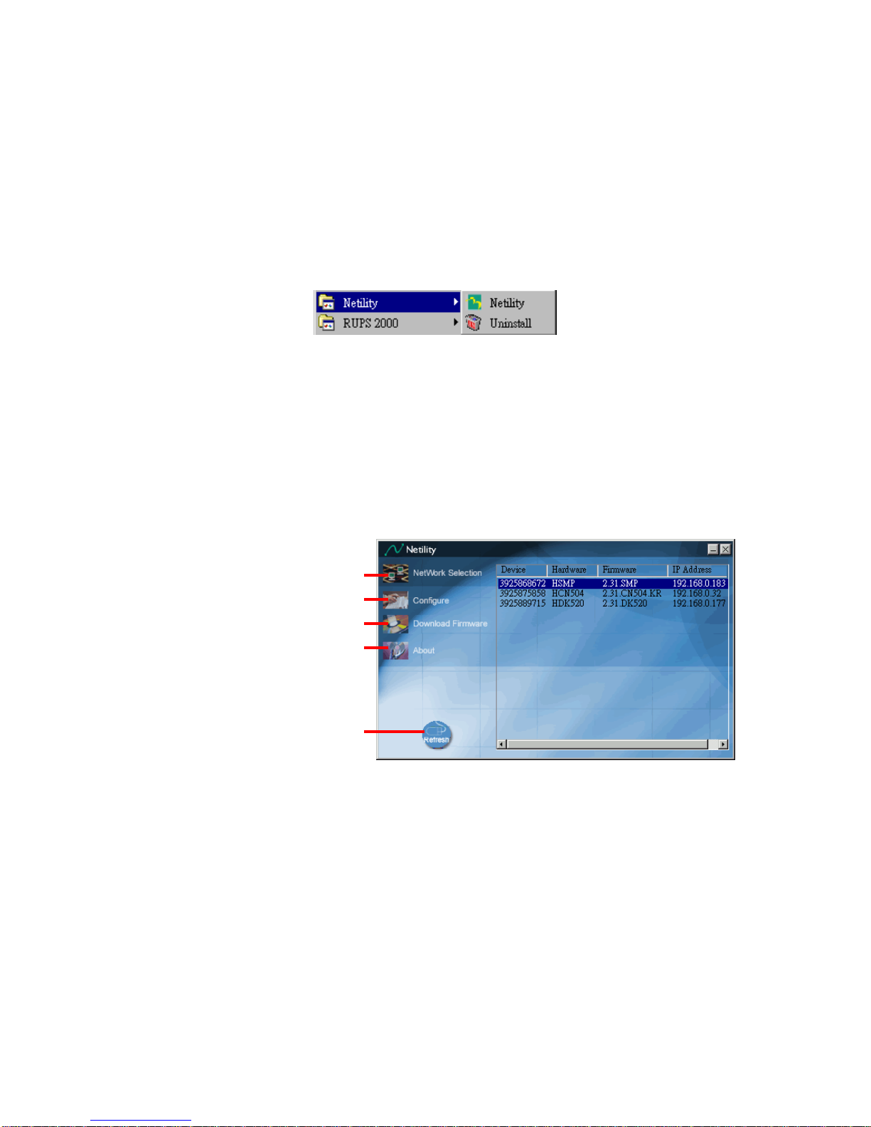
2. After installation is completed, ‘Netility’ group will appear in Windows ’Start’ Æ
‘Program Group’.
Netility Group
3. Click “Netility” to start the program.
3.2 Using Netility for IP Configurations
The Netility main menu is shown below. The selection menu is located on the left. The
device, hardware, firmware and IP addresses of all RPM connected to the LAN are
displayed on the right.
Netility Main Menu
3.2.1 NetWork Selection
Once Netility starts-up, it will automatically search for the computer’s Network card (If not,
click on “Network Selection” on the main menu to start the search). A pop-up window will
show the available Network Adapter.
Next, select the Network Adapter which is connected to the internet and click ‘OK’ to return
to the main menu. RPM current IP will now appear in the main menu display area.
nSelect Network card in you system
rConduct another search for
RPM on network
oConfigure RPM’s IP, etc.
pUpdate RPM Firmware
qAbout Netility
This manual suits for next models
2
Table of contents