Singer 2700 Series User manual

359109-000 AGO/03
27002700
Service Manual
Household Sewing
Machine
Series
THE SINGER COMPANY
2003 SINGER (SHANGHAI)
SEWING MACHINE CO., LTD.
ALL RIGHTS RESERVED
Registered Trademark “THE SINGER COMPANY LTD.” Printed In China

2700 - Revisions Records
Revision Description Approval
and date
01
AGO/03
Rev. n .
o
Service Manual
359109-000 AGO/03

This manual is designed for use by trained and qualified service
persons.
The SINGER COMPANY will not be responsible for any parts
requiring replacement due to natural wear or to the abuse or
negligence of its use or in the event the machine is serviced by
other than a trained and qualified service person or even if
replaced parts do not meet applicable specifications.
Service Manual
02
AGO/03
Rev. n .
o
359109-000 AGO/03

03
AGO/03
Rev. n .
o
359109-000 AGO/03
Scope
Machine Description
Tool requirements
This service manual describes all of the servicing procedures,including all adjustments and parts
removal and replacement for the 2700 class machine. Additional information covering any
production changes, improvements or changes to parts will be made by issuing Singer service/parts
bulletins.
Tubular bed.
Lightweight aluminium casting.
Apollo sewing system.
Electronic triac foot speed controller.
New "FT" fabric feed system.
Vertical needle profile.
Motor concealed in bed.
Horizontal spool pin.
Touch and wind declutching hand wheel.
Bobbin capacity of 41 m (45 yds) minimum.
Universal presser bar pressure control.
Maximum stitch lenght 5 mm (5 s.p.i.).
Self-threading take-up lever.
Push button instant reverse.
One-way needle insertion.
Direct pattern selection.
Drop feed system (Only for models 2722, 2724,2730 and 2732).
Four step buttonholer.
Automatic needle threading (Only for models 2730 and 2732).
Bed length 380 mm. (14.96 inches) without cloth plate.
Bed width 185 mm. (7.28 inches).
Bed height 83 mm. (3.27 inches).
Clearance under free arm 25,4 mm. (1.0 inch).
Free arm circunference 264 mm. (10.39 inches).
Overall height 310 mm. (12.20 inches).
Weight 7,6 kg. (16,6 lbs).
1/8" screwdriver
3/16" screwdriver
1/4" screwdriver
Philips screwdriver
8 mm. open end wrench
10 mm. open end wrench
Pliers
Wire-cutter pliers
Feeler gauge GM8092
Feeler gauge set.
1,5 mm Allen wrench
Straight tips external ring pliers (tip dia. 0,9 mm)
l
l
l
l
l
l
l
l
l
l
l
l
l
l
l
l
l
l
l
l
l
l
l
l
l
l
l
l
l
l
l
l
l
l
l
l
l
l
l
Extralong screwdriver (5,0 mm dia. x 380 mm long)
Service Manual
General Information

l
l
l
l
l
l
l
l
l
l
l
l
l
l
l
l
l
l
l
l
l
l
l
l
l
l
l
l
l
l
l
l
Parts removals and replacements.........................................................
Face plate.....................................................................................
Light bulb replacement.....................................................................
Bed bottomcover.............................................................................
Rear cover.....................................................................................
Front cover.....................................................................................
Needle bar.....................................................................................
Take-up lever assembly and needle bar connecting link..............................
Handwheel......................................................................................
Arm shaft and horizontal bevel gear.......................................................
assembly .
Thread tension assembly....................................................................
Motor and motor belt........................................................................
Hook...........................................................................................
Feed lifting lever assembly.................................................................
Feed rock shaft assembly..................................................................
Feed forked connection....................................................................
Vertical shaft bevel gear....................................................................
Vertical shaft.................................................................................
Stitch lenght and buttonhole control assembly ......................................
Arm top cover................................................................................
Face plate and lamp mounting bracket..................................................
Needle threader assembly (for model 2730/2732) .....................................
Needle bar vibrating bracket assembly ..................................................
Presser bar assembly.........................................................................
Cam controlled feed follower ..............................................................
Needle position lever ........................................................................
Cam controlled feed mechanism ..........................................................
Disk stack shaft gear and bracket assembly ............................................
Zigzag stitch width bracket assembly ...................................................
Disc follower quick out lever(For models 2718/2724/2730)...........................
Disc follower ...................................................................................
Pattern selector .................................................................
Table of Contents
Section I
06
07-08
07-08
09-10
11-12
13-14
15-16
17-18
19-20
21-22
23-24
25-26
27-28
29-30
31-32
31-32
33-34
35-36
37-38
39-40
39-40
41-42
43-46
47-48
49-50
51-52
53-56
57-58
59-60
61-62
63-64
65-66
PAGE
Service Manual
04
AGO/03
Rev. n .
o
359109-000 AGO/03

l
l
l
l
l
l
l
l
l
l
l
l
l
l
l
l
l
l
l
l
l
l
l
l
l
l
l
l
l
l
l
l
l
l
l
l
l
l
l
l
l
Sequential order of adjustment procedures ...............................................
Vertical shaft end play .........................................................................
Bevel gear mesh and arm shaft end play ..................................................
Disc follower height adjustment ...........................................................
Disc and disc follower clearance (For models 2718/24/30) ...........................
Disc stack radial play (For models 2718/24/30) .......................................
Disc and disc follower clearance (For models 2712/22/32) ...........................
Disc stack radial play (For models 2712/22/32) .......................................
Take-up lever and needle bar connecting link lost motion .............................
Needle bar bearings ...........................................................................
Needle bar height ..............................................................................
Needle bar pendulum timing ...............................................................
Zig-zag centralizing procedure ..............................................................
Centralizing center needle position........................................................
Centralizing left-right needle positions .................................................
Needle location in the needle plate slot ..................................................
Needle to hook relationship ..................................................................
Zig-zag lever bight stop in the straight stitch position .................................
Maximum width zig-zag lever bight stop .................................................
Needle bar safety bight stop (left side) ..................................................
Alignment of knobs with panel graphics ...................................................
Presser bar height and alignment ...........................................................
Hook drive belt tension .....................................................................
Hook drive belt retainer bracket .........................................................
Hook timing (hook and needle synchronism) ............................................
Bobbin case position finger .................................................................
Bobbin case position plate .................................................................
Bobbin case clearance .......................................................................
Needle Thread tension .......................................................................
Bobbin winder .................................................................................
Feed rock shaft end play ....................................................................
Feed dog centralization .....................................................................
Feed dog height ..............................................................................
Feed dog throw ...............................................................................
Stitch lenght regulator spring tension ....................................................
Motor belt tension ...........................................................................
Flexi stitch zeroing (accurate adjustment of the stitches) ..........................
Zero feed .....................................................................................
Buttonholer cutting space ...................................................................
Needle threader (For models 2730/2732)...............................................
Lubrication....................................................................................
67
68-69
70-71
72-73
74-75
74-75
76-77
78-79
80-81
82-83
84-85
86-87
88-89
90-91
92-93
94-95
96-97
98-99
100-101
102-103
104-105
106-107
108-109
108-109
110-111
112-113
112-113
114-115
116-117
118-119
120-121
122-123
122-123
124-125
126-127
128-129
130-131
132-133
134-135
136-137
138-141
PAGE
Service Manual
Table of Contents
Section 2
05
AGO/03
Rev. n .
o
359109-000 AGO/03

Section 1
Parts Removal and
Replacement
Service Manual
06
AGO/03
Rev. n .
o
359109-000 AGO/03

B
A
C
Service Manual
Light Bulb Replacement
Face Plate Cover
07
AGO/03
Rev. n .
o
359109-000 AGO/03

Removal:
Replacement:
Removal:
Replacement:
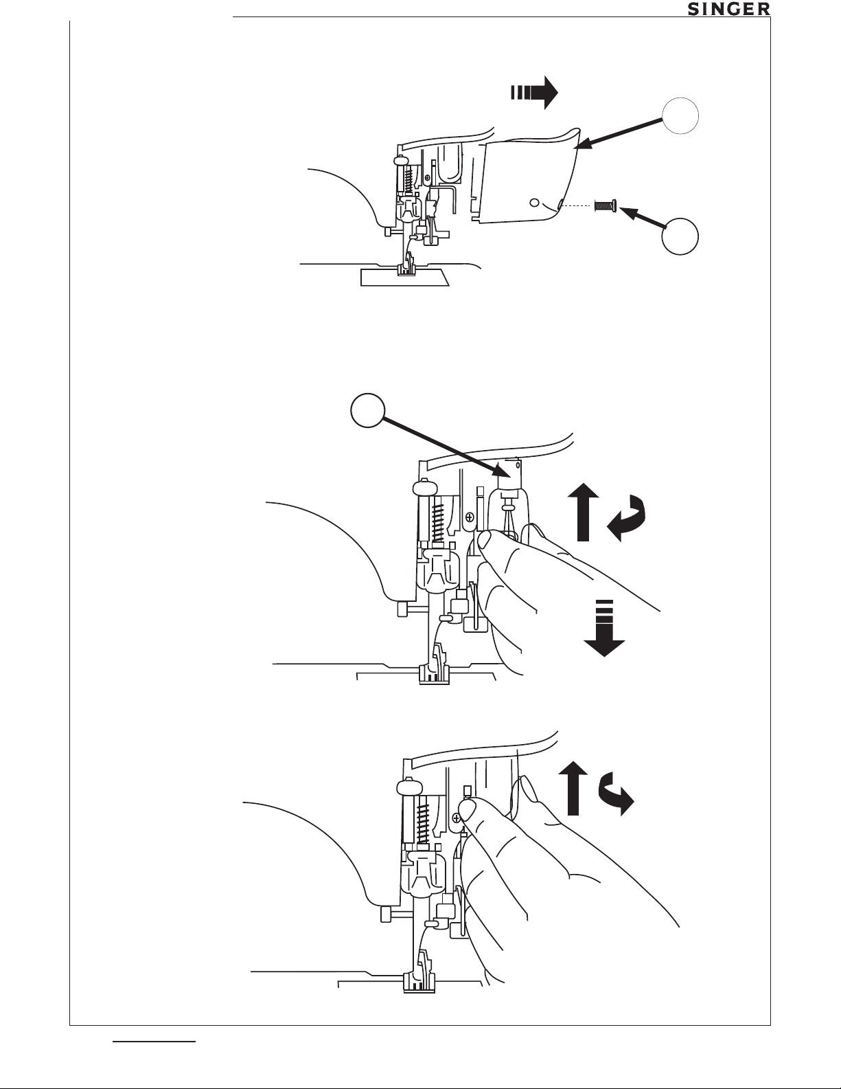
1. Raise presser foot.
2. Remove face plate cover screw (A).
3. Remove face plate cover (B) by pulling it down and laterally and then out of the
machine.
1. Replacement of the face plate cover is the same as described above, but in a reverse
order. Be sure the presser foot is in the raised position.
Turn the machine off and remove plug from outlet.
1. Remove face plate cover.
2. Push lamp (C) up and turn it clockwise.
3. The spring inside the socket, will push the lamp down and out the socket.
1. After inserting the lamp pins into the socket slots, push the bulb lamp (C) up and then
turn it gently counterclockwise.
Face Plate Cover
Service Manual
Light Bulb Replacement
08
AGO/03
Rev. n .
o
359109-000 AGO/03

Service Manual
C
A
B
Arm Top Cover
09
AGO/03
Rev. n .
o
359109-000 AGO/03
Table of contents
Other Singer Sewing Machine manuals

Singer
Singer 9985 User manual

Singer
Singer 8280 User manual

Singer
Singer 96-3 Installation and operation manual

Singer
Singer 301 User manual

Singer
Singer M1505 User manual

Singer
Singer 221 User manual

Singer
Singer 1409 User manual

Singer
Singer 457A105 User manual

Singer
Singer 147-110 Quick start guide

Singer
Singer 246-31 User manual

Singer
Singer MEDIUM Guide

Singer
Singer 251C User manual

Singer
Singer 6268 User manual

Singer
Singer 116-1 User manual

Singer
Singer SE017 User manual

Singer
Singer Style-Mate 329K User manual

Singer
Singer 231-34 Installation and operation manual

Singer
Singer 147-85 User manual

Singer
Singer SUPERA User manual

Singer
Singer 250 Series User manual