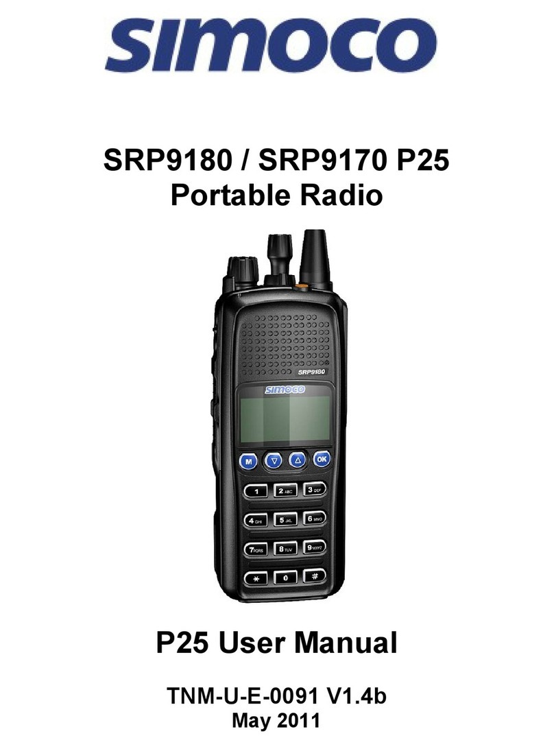
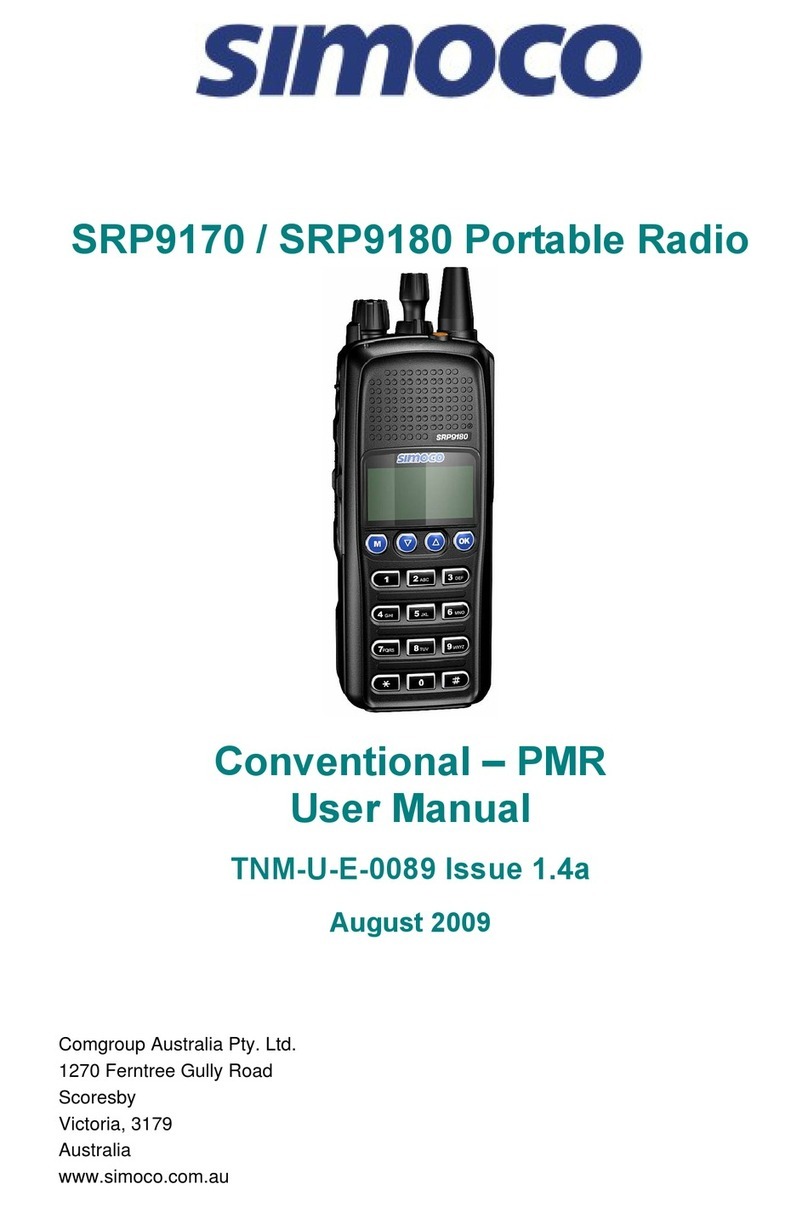
Simoco SRP9170 User manual

SRP9170/SRP9180 Portable Radio
MPT1327 Portable
Radio User Manual
TNM-U-E-0090 Issue 1 3a
January 2010
Comgroup Australia Pty. Ltd.
1270 Ferntree Gully Road
Scoresby
ictoria, 3179
Australia

SRP9180 ~ MPT1327 Portable Radio User Manual
© Comgroup Australia 2010 page 2 TNM-U-E-0090 Issue 1.3a
Associated Documentation
The following documentation is available for the SRP9180 series of products:
TNM-U-E-0088 SRP9180 PMR Brief User Guide
TNM-U-E-0089 SRP9180 PMR User Manual
TNM-U-E-0091 SRP9180 P25 User Manual
TNM-U-E-0095 SRP9180 P25 Brief User Guide
TNM-U-E-0102 SRP9180 Brief User Guide (General)
To order copies of any of the above publications, or any other Simoco product, contact
Comgroup Australia on +61 3 9730 3800 or send a Fax on +61 3 9730 3968.
About This Document
This publication is copyright and no part may be reproduced without prior permission of
Comgroup Australia.
Due to our policy of continuous improvement to our products and services, technical
specifications and claims, correct at time of publication, may be subject to variation without
prior notice.
Comgroup Australia has endeavoured to ensure that the information in this document is fairly
and accurately stated, but does not accept liability for any errors or omissions.

SRP9180 ~ MPT1327 Portable Radio User Manual
© Comgroup Australia 2010 page 3 TNM-U-E-0090 Issue 1.3a
General Safety
1. Do not operate your portable radio whilst driving a vehicle
2. Do not operate your radio in an explosive atmosphere
Obey the 'Turn Off Two-way Radios' signs where these are posted, e g on a
petrol station forecourt
3. Do not dispose of batteries in a fire
4. Only recharge batteries in an approved SRP9180 Charger
IECEx Intrinsically Safe Radios
Radio models approved for use in hazardous environments according to the IECEx Scheme
are marked with an approval number.
Refer to the label on the radio for the IECEx compliance level.
The following MUST be observed to maintain the IECEx protection rating:
• Use only approved SIMOCO battery, part number PAR-9180BATL2i or PAR-9180BATL3i
.
• Battery charging must only be carried out in non-hazardous areas, using an approved
battery charger.
• Metal belt clips must NOT be used in hazardous areas.
• It is a requirement that when the radio is used in a hazardous area that either the SRP9180
Accessory Cover Assy (6102 350 1446) or an approved Simoco IECEx accessory is fitted
(refer Section 8 for list of approved accessories).
• Approved accessories may only be connected and disconnected outside the hazardous
areas.
• Prior to use in a hazardous area, inspect the radio and accessories for signs of damage.
Any visible signs of damage to the radio or accessories may compromise the integrity and
safety of the radio. A damaged radio or accessories must be repaired or replaced prior to use
in a hazardous area.
• Incorrect storage, handling or operation of the radio and accessories, as specified in
Simoco published User Guides and Service Manuals, may compromise the safety and
integrity of the radio or accessories.
• Approved labels stating the IECEx rating level must be on the radio and accessories, and
be legible, before their use in a hazardous area.
Hints for Using the Radio
• When speaking, hold the radio a few centimetres from your mouth and speak across it,
rather than into it. The microphone is located near the bottom right hand corner of the
portable radio’s speaker grille.
• Keep the length of your conversation to a minimum to conserve battery life.
• When it is possible to move location, avoid making calls from known poor signal-strength
areas such as the radio system’s fringe areas (limit of range) or from screened or
shadowed areas, e.g. an underground car park or underpass.

SRP9180 ~ MPT1327 Portable Radio User Manual
© Comgroup Australia 2010 page 4 TNM-U-E-0090 Issue 1.3a
CONTENTS
1 INTRODUCTION 6
1 1 Overview 6
1 2 Configuration 6
1 3 Conventions 6
2 FRONT PANEL CONTROLS 7
3 MENU SYSTEM 8
3 1 Menu navigation 8
4 MAIN MENU SCREENS 10
4 1 Phonebook Screen 10
4 2 Stored Calls Screen 11
4 3 Status Screen 13
Call Types Screen 14
4 4 Send Message Screen 14
4 5 Setup Screen 14
5 COMMON FUNCTIONS AND FACILITIES 15
5 1 Switch-On/Switch-Off 15
5.1.1 In-Service Indication................................................................................ 15
5.1.2 olume Adjustment ................................................................................. 15
6 CALL TYPES 16
6 1 Making a Voice Call 17
6.1.1 During a oice Call ................................................................................. 17
Making a Status Call 18
6.1.1 Using the Phonebook.............................................................................. 18
6.1.2 By Dialling the Numbers.......................................................................... 18
6 2 Receiving a Call 19
6.2.1 Receiving an Individual oice Call .......................................................... 19
Receiving a Group oice Call ............................................................................... 20
6.2.2 Incoming Status and Data Messages...................................................... 20
6 3 Call Diversion 21
6.3.1 From the Call-Types Screen ................................................................... 21
6.3.2 By Dialling the Numbers.......................................................................... 21
6.3.3 To Cancel a Diversion............................................................................. 21
6 4 DTMF Operation 22
7 SETUP 23
7 1 Setup sub-menus 23
7.1.1 User Options ........................................................................................... 23

SRP9180 ~ MPT1327 Portable Radio User Manual
© Comgroup Australia 2010 page 5 TNM-U-E-0090 Issue 1.3a
7.1.2 Group ...................................................................................................... 23
7.1.3 Phone Book Edit Menu ........................................................................... 24
7.1.4 Contrast................................................................................................... 26
7.1.5 Alert olume............................................................................................ 26
7.1.6 Radio Information.................................................................................... 27
7.1.7 Mode/Network Selection ......................................................................... 27
8 OPTIONS 28
8 1 Lithium Ion Battery (PAR-9180BATL2x) 28
8 2 Lithium Ion Battery (PAR-9180BATL2) 28
8 3 Lithium Ion Battery (PAR-9180BATL3i) 28
8 4 Lithium Ion Battery (PAR-9180BATL3) 28
8 5 Single Pocket Charger (PAR-9180CRG1) 28
8 6 Two Pocket Charger (PAR-9180CRG2) 28
8 7 Six Pocket Charger (PAR-9180CRG6) 28
8 8 Vehicle Mounted Charger (PAR-9180CRGV) 28
8 9 Lightweight Carry Case (PAR-9180CLBC2) 28
8 10 Lightweight Carry Case (PAR-9180CLBC3) 28
8 11 Heavy Duty Carry Case (PAR-9180CHSM) 28
8 12 Lightweight Lapel Function Speaker Microphone (PAR-9180LMS2) 28
8 13 GPS Microphone (PAR-9180LMGM) 28
9 TROUBLESHOOTING 29
10 APPENDIX A – ALERT TONES AND MESSAGES 30
11 APPENDIX B - DIAL STRINGS AND NUMBERING CONVENTIONS 31
Dial Strings ........................................................................................................... 31
12 APPENDIX C - GLOSSARY 33
13 COMPLIANCE WITH RF ENERGY EXPOSURE GUIDELINES (UNITED
STATES AND CANADA) 34

SRP9180 ~ MPT1327 Portable Radio User Manual
© Comgroup Australia 2010 page 6 TNM-U-E-0090 Issue 1.3a
1 INTRODUCTION
1 1 O
VERVIEW
The SRP9180 Series Radio is a versatile Digital Signal Processor (DSP) controlled, two-way
portable radio. The SRP9180 Series Radio is available in a number of frequency bands for
specific applications.
The radio is software programmable and can be customised to the operational requirements
of your particular fleet. Your Simoco representative can help in programming your radio
facilities to meet your present and future requirements.
A wide-range of accessories is available to complement the SRP9180 Series Radio
including: chargers, antenna, headsets, covert kits, holsters and carry cases. Refer to
Simoco website for comprehensive descriptions.
This guide describes the facilities that are currently available and can be programmed into
the MPT1327 Trunked Mobile Radio (TMR) mode of the SRP9180 series.
1 2 C
ONFIGURATION
Before you can use the SRP9180, it must be configured using the Field Personality
Programmer (FPP). This configuration process loads the customised channels, signalling
and user options so the radio will operate with your system.
The FPP will also update the radio software automatically, if required.
1 3 C
ONVENTIONS
Where the word “generally” or “may” is used to describe a facility, this operation is an option
that may be enabled with the FPP.
References to the SRP9180 also apply to the non-keypad version (SRP9170) except where
keypad operation is described.

SRP9180 ~ MPT1327 Portable Radio User Manual
© Comgroup Australia 2010 page 7 TNM-U-E-0090 Issue 1.3a
2 FRONT PANEL CONTROLS
Accessory
Connector
Function #7
Selector Switch
ABC Switch
On/Off olume
PTT
Function #5
Function #6
Function #2
Function #1
Function #3
Function #4
Antenna
Keypad
Indicator LED
Figure 1 SRP9180 Portable Layout
KEY / CONTROL FUNCTION
On/Off/ olume Rotate the switch clockwise to turn on the radio and then set the
volume to the desired level.
Selector Switch Rotate to select Phone Book entries.
ABC Switch May be programmed to change radio Modes or Networks.
Rx/Tx/Power LED Green LED illuminates when receiving a signal. Red LED illuminates
when the radio is transmitting. Flashing Red LED indicates low battery.
PTT Push-to-Talk. Hold the radio 10cm from the mouth. Press and hold the
PTT switch and speak. Release to listen.
Keypad Used to enter Idents, send text messages and set status.
Function Key F1 M Programmable function key. It is typically programmed as the Menu
Select key.
Function Key F2 ▼ Programmable function key. It is typically programmed as the Down
key.
Function Key F3 ▲ Programmable function key. It is typically programmed as the Up key.
Function Key F4 OK This function key may be configured by the programmer. Note that
during menu operations it becomes the Confirm key.
Special Function F5 Programmable function key.
Special Function F6 Programmable function key.
Special Function F7 Programmable function key. It is typically programmed as the Alarm /
Emergency key.

SRP9180 ~ MPT1327 Portable Radio User Manual
© Comgroup Australia 2010 page 8 TNM-U-E-0090 Issue 1.3a
3 MENU SYSTEM
The SRP9180 radio software uses a programmed menu structure to enable the operator to
access the radio options. The structure of the menu can be configured to meet the
customer’s specific needs using the FPP.
Figure 2 (overleaf) illustrates the menu structure of the radio. Note that the order and
presence of each menu is determined by the configuration of the radio programmed by the
FPP.
There are Setup sub-menus that provide access to radio setup parameters.
Possible Menu entries are:
• Phone Book
• Recall
• Stored Calls
• Call Types
• Status
• Setup
• User Options
• Group
• Phone Book Edit
• Alert olume
• Radio Information
• Mode Selection or Network Selection
• Received Signal Strength Indication (RSSI)
• Send Message
To assist the user in menu key selection, a soft menu label will often appear above the
function keys. The label shows the user the current function for that key which may change
between different menus.
Programming of menus is a configuration task normally performed by the System Manager
using the FPP.
3 1 M
ENU NAVIGATION
The M key is generally used to select Menu mode from the main Screen. Once in Menu
mode, the ▼ ▲ keys cycle through the menus.
To exit Menu mode, press the M key again or the Menu timeout will exit automatically.
Generally, pressing the M key while in a menu backs up to the next highest level of menu
and the OK key selects the function.
The ▼ ▲keys are generally used to navigate through a list of options Phonebook entries, or
to increase or decrease a value.

SRP9180 ~ MPT1327 Portable Radio User Manual
© Comgroup Australia 2010 page 9 TNM-U-E-0090 Issue 1.3a
Menu System
PHONE
BOOK
Menu
Menu
Menu
Menu
Menu
STORED
CALLS
CALL
TYPES CALL
TYPES
RECALL
STATUS
SETUP
STATUS
RECALL
STORED
CALLS
ENTRY POINT
Scroll through
Phonebook
Entries
Note:
Example Menus only shown.
MPT1327 TNK Menu rev2
Other Menus may be configured with the FPP
Up Key
Down Key
'M' Key (same as ’BACK’)
OK Key
SubMenu Selections
Edit Menu
Edit Menu
PHONEBOOK
PHONEBOOK
CONTRAST
GROUP
ALERT OL.
RADIO INFO.
NETWORK.
Menu
Menu
Menu
Menu
User Options
NETWORK
RADIO
INFORMATION
ALERT
OLUME
CONTRAST
GROUP
KEY BEEPS
ON/OFF
BACKLIGHT
ON/OFF
DTMF
ON/OFF
'M'
OK
Default Screen
OK
OK
OK
OK
OK
OK
OK
'M'
'M'
'M''M'
'M''M'
'M'
OK
'M''M'
'M'
'M''M'
'M'
OK
OK
OK
'M''M'
'M'
'M'
'M'
'M'
'M'
'M'
'M'
OK
'M''M'
Figure 2 - Menu Navigation

SRP9180 ~ MPT1327 Portable Radio User Manual
© Comgroup Australia 2010 page 10 TNM-U-E-0090 Issue 1.3a
4 MAIN MENU SCREENS
4 1 P
HONEBOOK
S
CREEN
The Phonebook allows calls to be made to entries from the Phonebook list.
The RSSI Bars indicate the
signal strength of the current
Control or Traffic channel.
The Name Field shows the
current selected entry from
the Phonebook.
Displayed Labels show the
function of the F1 and F4 keys.
Pressing the key below will set
the function.
The Icon Line displays
various icons as described
in the table below.
The Message Line provides
information about what the radio
is doing, e.g. Call-setup,
Queued, Diverted, etc.
Pressing the ▼ ▲ keys or rotating the top Selector Switch selects the Name Field entries.
Press the OK (call) key to call the Name Field entry.
The Keypad may be used to enter dial-strings directly.
Several Icons can be displayed as shown below:
ICON INDICATION
The rotating arrow icon shows that the radio is registering with the Trunk
Network. It disappears when the radio is In Service.
The envelope icon indicates that there are one or more stored calls (in the
Stored Calls menu).
The outline speaker icon indicates that speaker audio is muted, e.g. during Call
Setup, NPDs, etc.
The filled speaker icon indicates that speaker audio is enabled, e.g. during a
Call.
The asterisk symbol indicates Call Pending, i.e. there is an outgoing call
waiting for the radio to be In Service.
The key icon indicates that the keypad lock function is activated.
*
Other manuals for SRP9170
2
This manual suits for next models
1
Table of contents
Other Simoco Portable Radio manuals

Simoco
Simoco SRP8000 SERIES User manual

Simoco
Simoco SPR180 User manual

Simoco
Simoco P25 User manual

Simoco
Simoco SRP9180-P25 User manual

Simoco
Simoco SDP760 User manual

Simoco
Simoco SRP9170 User manual

Simoco
Simoco SDP660 User manual

Simoco
Simoco SRP9100 User manual

Simoco
Simoco SDP560 User manual

Simoco
Simoco SRP9120 Instruction Manual